


-
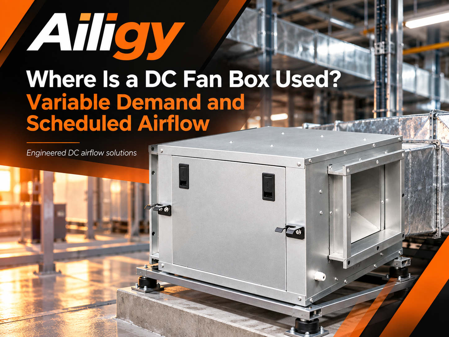 DC fan cabinets are mainly used for air supply and exhaust systems that need to adjust the air volume on demand. They are especially suitable for projects where the operating period, regional load or the number of equipment turned on will change. Time-sharing operation is the most typical usage scenario. The speed can be switched according to work, duty and other modes to reduce the input power during low load periods. Demand air can also manage regional load changes, but reducing the speed will also change the pressure available, and it must be verified that the most unfavorable end still meets the requirements. New projects can unify control interfaces during the design phase, while renovation projects must first take stock of the original control signals, power supply capacity, and maintenance space. To judge applicability, it is necessary to provide the design air volume, common air volume, corresponding external static pressure, operating period, most unfavorable end demand, power supply conditions, speed control signal type and installation conditions. Aili Industrial can discuss the configuration of the DC fan chassis according to actual working conditions, and the division of labor boundaries with EFU, FFU, high-efficiency air supply vents and other equipment will be clearly defined on the system flow chart.
-
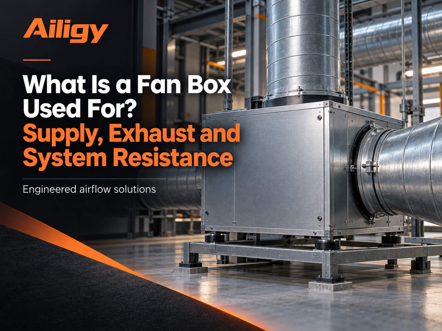 This article explains the role of the fan box in air supply and exhaust from the system position, and distinguishes between power equipment and terminal filter equipment. The fan box is mainly used to provide air supply and exhaust power for air ducts or equipment, and is suitable for systems that need to overcome the resistance of pipelines and components. Air supply, exhaust and pressurization are three typical uses. Different uses have different selection boundaries. The fan box does not directly define the air cleanliness level. Cleaning projects need to separately determine terminal solutions such as high-efficiency air supply outlets, HEPA/ULPA filters or FFU. To determine whether the purpose is matched, air supply or exhaust, design air volume, external static pressure, air medium, operating time, control method and installation conditions should be provided. Only by knowing the position of the fan box in the entire air path can the box structure, fan curve and maintenance direction be determined.
-
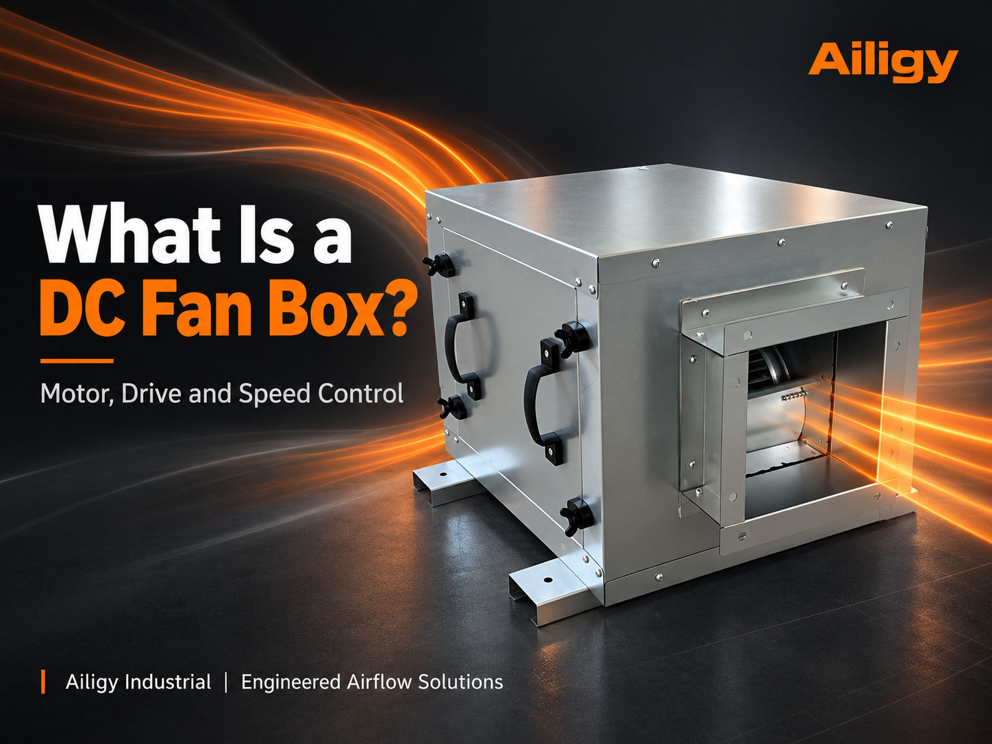 The DC fan box drives the fan with a DC or electronically commutated power system. Only by understanding the cooperation of motors, drives and control signals can you judge whether it is suitable for a new construction or renovation project. The rated power of the motor is used to define the capacity of the motor, and the input power of the fan box is the actual power consumption of the whole machine under specific working conditions. The two are not the same number. When making an inquiry, you should confirm the speed control signal, start and stop methods, fault feedback and minimum operating air volume.
-
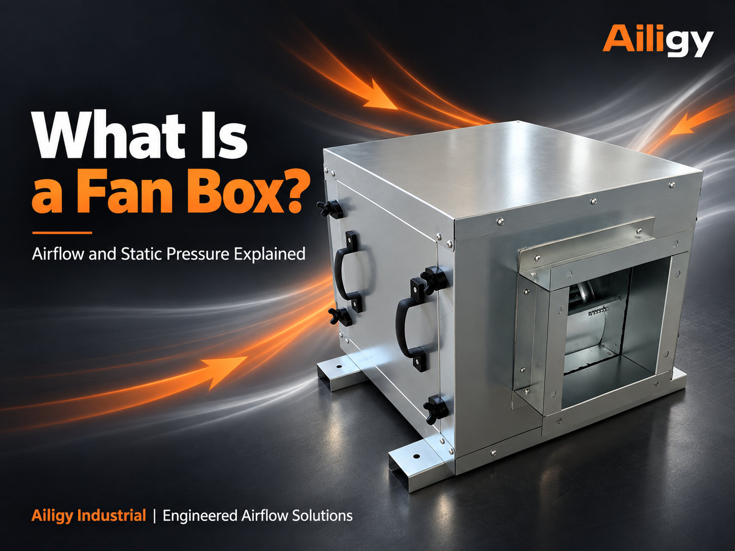 The fan box is a combined device that provides air supply and exhaust power to the air duct or equipment. This article explains its boundaries with filters and FFU, as well as the selection method based on air volume and system resistance. The air volume is sufficient when the same typhoon chassis is connected to a short air duct, but cannot meet the end requirements after being connected to a new filter section and long air duct. This is not necessarily a motor failure.
-
 Comparison between DC and AC fan chassis should be done under the same air volume, static pressure and operating time, focusing on checking the overall machine power, speed adjustment method, control interface and maintenance conditions. If the old equipment on site relies on valve throttling for a long time, first measure the actual terminal air volume and pressure before discussing modification. The difference usually appears in the control strategy and operating mode. AC frequency conversion can also adjust speed, and the DC solution does not naturally save power. The procurement conclusion should list the power supply, control protocol, operating point, noise, box interface and total investment in the same comparison table, and indicate the test conditions. Aili Industrial has the ability to independently support fans, motors, controls and sheet metal. It can calibrate impellers, motors, drives and cabinets at the same working point, and provide complete machine test data according to project conditions, allowing comparisons between DC and AC to be based on verifiable complete machine data.
-
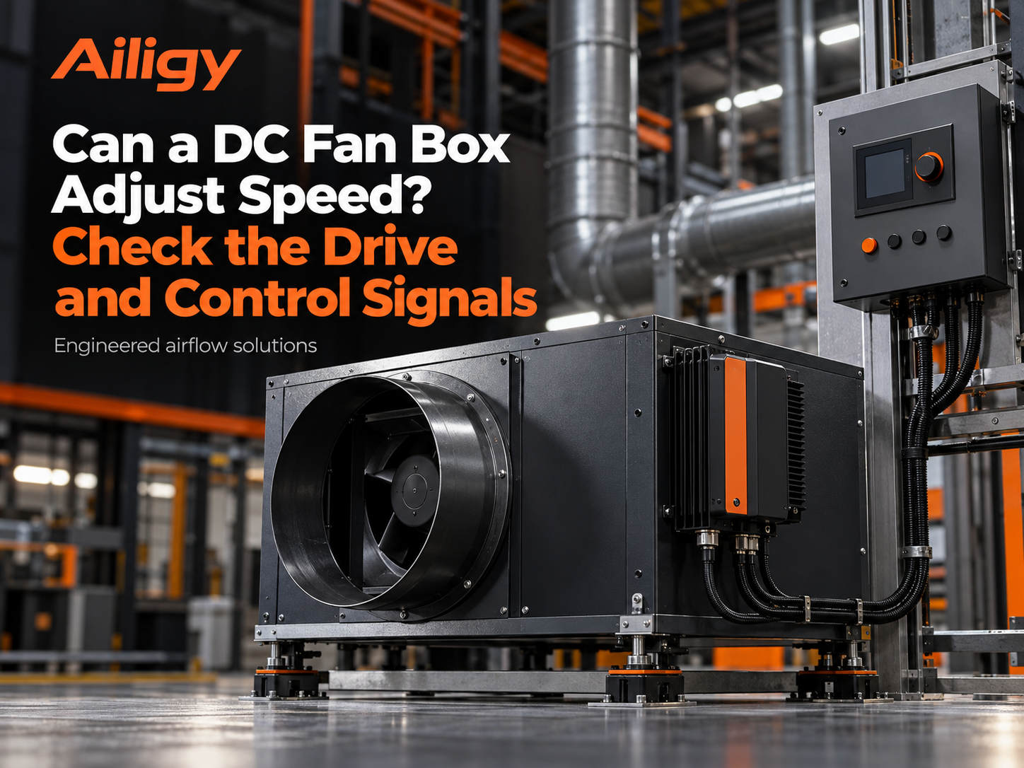 The speed of the DC fan box can be adjusted, but the driver signal, minimum air volume and actual measured air volume calibration need to be checked. The speed regulation capability comes from the driver. Different drivers may have different definitions of analog, PWM and communication signals. The electrical diagram and terminal description should be checked before on-site wiring. During debugging, the controller gives a 50% command, which does not mean that the actual air volume must be half of the rated value. The air volume, static pressure and input power should be measured at several typical command points to form a corresponding table. The minimum operating air volume should be determined by the terminal demand, and the fault action and response after disconnection should be confirmed before leaving the factory. To interface with the on-site control cabinet, a control point table is required to clarify the signal type, range, terminal definition and feedback method. Aili Industrial has independent supporting capabilities for motors, fans and controls. EC motors and drives can match parameters according to the project control point table, reducing interface incompatibilities and on-site modifications.
-
 To save energy in a DC fan chassis, it is necessary to simultaneously compare the motor drive efficiency and period-by-period speed regulation benefits at the same operating point. EC motors use permanent magnet rotors, which have low rotor losses and have a flatter efficiency curve than AC motors under partial load conditions. When comparing, it is necessary to lock in the same air volume and external static pressure, and read the input power of the whole machine; just looking at the motor nameplate efficiency or rated power cannot represent the actual system power consumption. Directly comparing the power consumption of the old AC fan at excessive air supply to the power consumption of the new DC fan at lower air supply, the calculated power savings do not account for the difference in motor efficiency. The air volume, static pressure, power and annual operating hours of each mode should be recorded separately. The power of each mode is multiplied by the number of hours and then summed to obtain the estimated annual electricity consumption. The measuring points, filter status and valve openings of the old and new systems must be comparable, otherwise the calculated energy savings will have no engineering significance. Aili Industrial has independent supporting capabilities in fans, motors, controls and sheet metal structures. EC motors and fan impellers can be jointly calibrated according to the target operating point. The driver parameters and fan curves are set correspondingly, so that the speed regulation range can be determined around the actual operating conditions of the project.
-
 Ordinary fan boxes are not a unified motor category. Before comparison, you should confirm whether the original equipment has AC fixed speed, AC variable frequency or other configurations, and then check the operating point and control method. The efficiency of EC motors is significantly higher than that of AC motors under partial load conditions, but the actual energy savings depends on the load curve and speed regulation strategy. For example, write the requirement as 'Continuous operation under a certain air volume and a certain external static pressure requires two speed adjustments. See the drawing for the installation location and direction of the air outlet.' Then explain whether the original machine is AC fixed speed or AC variable frequency. In this way, each company's quotation corresponds to the same delivery scope, and it is easy to check whether the driver, control line and vibration reduction accessories are missing.
-
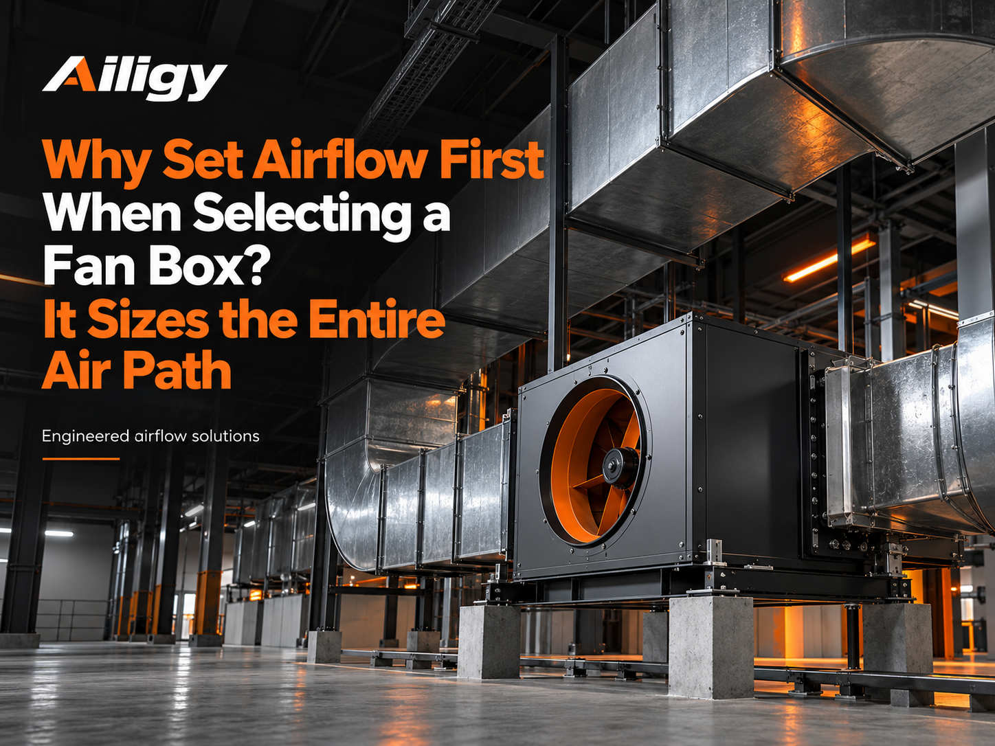 The air volume is determined before fan box selection because it affects branch distribution, air duct size and system static pressure. The air volume comes from the heat and moisture load, fresh air volume, process exhaust or cleanliness requirements of the service object. The maximum air volume on all equipment nameplates cannot be simply added up. The air volume determines the wind speed, the wind speed determines the pipe diameter, and the resistance changes with the square of the wind speed. Therefore, if the air volume is set too high or too low, it will affect the operation of the system. Renovation projects should first measure the actual terminal air volume and pressure difference, and cannot directly place an order based on the nameplate of the original machine. After the air volume is determined, the external static pressure must be calculated along the most unfavorable path to form an operating point on the fan performance curve. Aili Industrial has the capabilities to support fans, motors, controls and sheet metal. It can check the complete machine configuration based on zoned air volume, pipeline resistance and installation interfaces, so that drawings, quotations and acceptance data correspond to the same set of conditions.
-
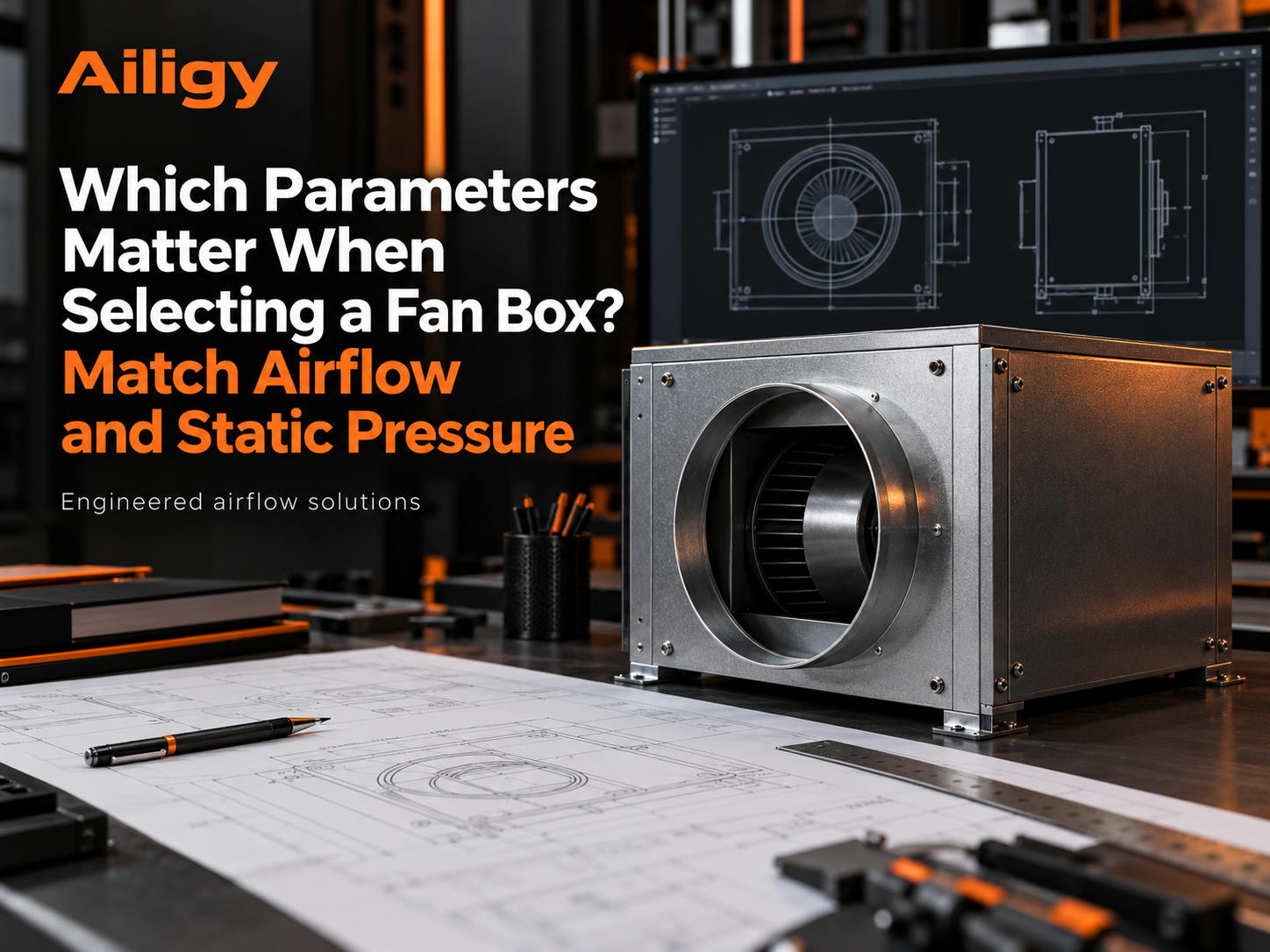 The selection parameters should be checked in groups: air volume, external static pressure, overall machine power, noise and installation control interface. The air volume must correspond to a certain external static pressure, and the nominal maximum air volume and maximum static pressure are usually not at the same operating point. System resistance comes from filter sections, coils, air valves, mufflers, elbows and the most unfavorable branches. The clean system should separately understand the filter cleaning status and the allowable pressure difference before maintenance. When reviewing supplier data with performance curves, you should confirm that the design operating point falls near the high-efficiency zone and allow for adjustment margin to deal with changes in resistance. Mechanical and electrical parameters cannot be left to the end. The direction of the air outlet, flange, foundation, maintenance space, power supply and control interface should all be confirmed during the selection stage. Aili Industrial has the capabilities to support fans, motors, controls and sheet metal. It can check the parameters of the entire machine according to the project working conditions, so that the drawings, quotations and acceptance data correspond to the same set of conditions.
-
 When selecting a DC fan chassis, the design operating point, common low-load operating conditions and drive control interfaces should also be considered to avoid determining equipment based solely on rated air volume. At least two sets of working conditions should be given: the air volume and external static pressure under the maximum design demand, and the partial load air volume under which the system often operates. For differential pressure control systems, also specify the sensor location and differential pressure target. The electrical configuration and mechanical conditions need to be checked together, including on-site input power, drive cooling, start-stop logic, speed control signals and fault feedback. 'Design air volume—design external static pressure—allowable input power' and 'common air volume—corresponding external static pressure—expected operating hours' can be listed separately in the technical list. During acceptance, the air volume, static pressure, complete machine power and control actions of the two working conditions should be written as measurable conditions. Aili Industrial can discuss the configuration of the DC fan chassis based on the motor, fan and control supporting capabilities.
-
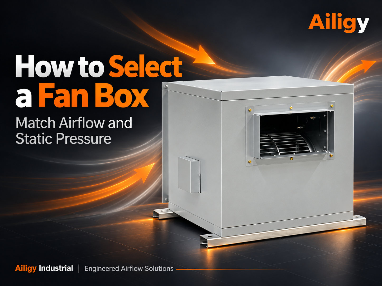 When selecting a fan box, the design air volume and system resistance should be combined into a working point, and then the performance curve, noise, power supply, installation and maintenance conditions should be checked. The design air volume should be summarized from the terminal demand, and the system resistance should be taken into account in the filter section, coil, elbow, valve and the most unfavorable branch. When the cleaning or air conditioning system has a filter section, the cleaning status and the allowable pressure difference before maintenance should be understood separately. The working point should be located near the high-efficiency area of the fan, and the noise, power supply, maintenance space and control interface should be checked. The fan law shows that the air volume is proportional to the rotational speed, and the shaft power is proportional to the cube of the rotational speed. The selection must be based on the actual operating point. The selection checklist includes design air volume, external static pressure, usage, power supply, operating time, air outlet direction, noise requirements and interlocking requirements.
-
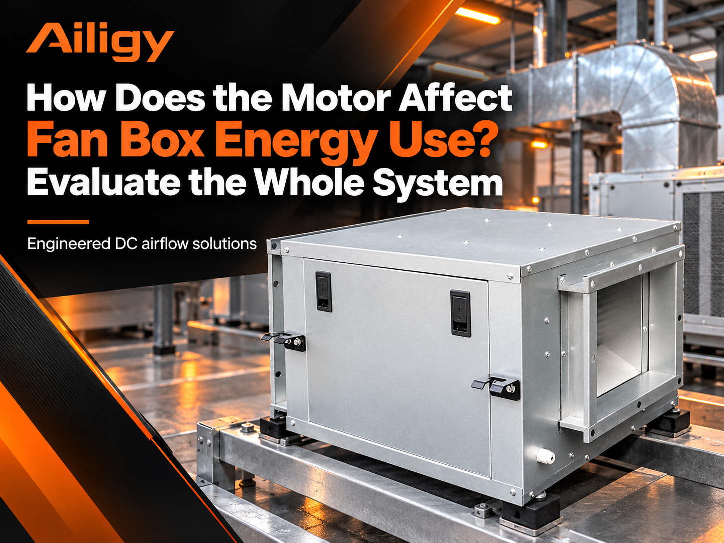 The motor affects efficiency and speed regulation capability, but the energy consumption of the fan box should be judged based on the complete machine power under the same air volume and static pressure. Motor efficiency describes the electrical energy conversion capability of the motor itself, while the input power of the entire machine includes motor losses, driver losses, fan aerodynamic efficiency and box internal losses. The impeller does not match the target air volume and pressure, and the air path loss inside the box is too large, which may offset the motor efficiency advantage. The ability to adjust the speed expands the value of the motor, but reducing the speed also reduces the pressure that can be delivered, and it is necessary to check whether the most disadvantaged end still meets the demand. Renovation requires unified measurement boundaries. Before replacing the motor, the air volume, static pressure and meter power of the original equipment under the same valve and filtration state should be recorded. Aili Industrial has the ability to independently support fans, motors, controls and sheet metal. It can calibrate impellers, motors, drives and cabinets at the same working point, reducing common matching deviations in outsourced assembly solutions and allowing energy consumption comparisons to be based on complete machine test data.
-
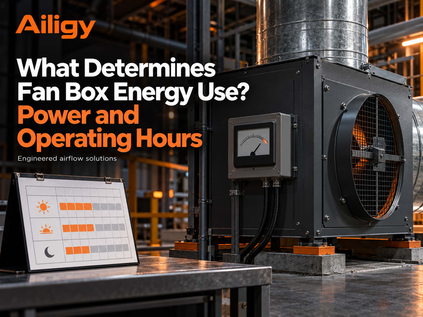 The operating energy consumption is determined by the input power of the whole machine and the operating time of each working condition, and cannot be directly replaced by the motor nameplate power. The same typhoon chassis has different input power under different air volume, static pressure, rotation speed and filter status. Increased system resistance, dust accumulation on the filter, air duct leakage and excessive valve throttling will all cause the fan box to operate in an unsatisfactory state for a long time. The annual power consumption should be recorded separately according to the working, duty and peak modes such as power and operating hours, and then multiplied one by one and then added together. The price of electricity only affects the amount of charges and does not change the power consumption of the equipment itself. If the terminal air volume is different before and after the transformation, the working conditions should be corrected first before discussing energy-saving benefits. The control method determines the power in each period. Speed regulation can reduce the input power during part of the load period, but the premise is that there is an adjustable load change in the system. Aili Industry has the ability to independently support fans, motors, controls and sheet metal. It can calibrate impellers, motors, drives and cabinets at the same working point, so that energy consumption calculations are based on the test data of the whole machine.
-
 To save energy in the fan box, you can first check the air leakage and resistance of the air duct, then adjust the on-demand air supply strategy, and finally evaluate the motor, fan and drive plan. On-site measurements often reveal uneven adjustment of branch valves, filters that have not been maintained for a long time, or air duct leakage. First deal with these system losses, and then select the motor and fan box according to the corrected system curve. If equipment is replaced and pipelines are significantly modified at the same time, it is recommended to record the data before and after each adjustment to facilitate the determination of where the energy savings mainly come from. Compare the input power of the equipment before and after the transformation under the same air volume and static pressure, and calculate the drive, construction and maintenance costs at the same time. Speed regulation and energy saving depends on the load curve and operation strategy. You cannot promise a fixed power saving ratio just by relying on the word 'DC'.
-
 Fan box energy consumption depends on the input power and duration of each operating period, not the nameplate power. When analyzing energy consumption, the design peak, daily operation and duty modes should be distinguished, and kilowatt hours should be accumulated according to the annual operating conditions. Assume that a system has different working periods and low-load periods every day. Record the complete machine power and hours in the two periods respectively, and then total the kilowatt-hours based on the number of operating days per year. The price of electricity only affects the cost and does not change the power consumption of the equipment. If the terminal air volume is different before and after the transformation, the working conditions should be corrected first, and then the energy saving benefits and payback period can be discussed. Energy-saving analysis cannot only focus on the motor. Long-term valve throttling, high air volume setting, abnormal filter resistance or air duct leakage will cause additional energy consumption. Only when the old and new solutions meet the same air supply requirements will the power comparison be meaningful.
-
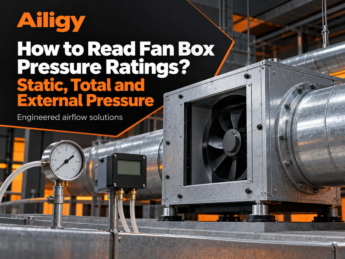 The wind pressure parameters must first identify the static pressure, total pressure and external static pressure, and then form a testable working point with the target air volume. The total pressure is the sum of static pressure and dynamic pressure. The external static pressure is the available part of the static pressure minus the internal losses of the unit. What engineers really use to overcome the resistance of the external pipeline is the external static pressure. When the equipment data is written as 'rated wind pressure', the corresponding air volume and test boundaries should be obtained from the supplier to confirm whether the pressure loss of the internal filter section or silencing section of the unit has been deducted. From the air outlet of the fan box to the most unfavorable end, the friction losses of the filter section, coil, valve, muffler, elbow and air duct should be totaled one by one according to the same design air volume. On-site pressure measurement should unify the pressure taking method, instrument range and measuring point location. Segmented pressure measurement can help locate abnormal local losses. High pressure does not necessarily mean sufficient air supply. Air volume, pressure and valve status should be judged together. Aili Industry has the ability to independently support fans, motors, controls and sheet metal, and can provide the external static pressure data of the entire machine under specified air volume to avoid caliber deviations between the sample full pressure, on-site static pressure and the designed external static pressure.
-
 To understand the air volume parameters, you need to check the unit, measuring point, external static pressure and fan performance curve at the same time. The maximum air volume is usually measured without external resistance or under specific test conditions and cannot be directly regarded as the design air volume. After selecting the external static pressure required for the project, read the corresponding air volume on the performance curve to determine the operating point that can be used for model selection. The air volume at the outlet of the fan box and the actual air volume obtained at the end may be different due to air leakage, not included in the branch circuit, or different measurement methods. When troubleshooting, first unify the measurement method and then check section by section. The variable load system should write down three groups of air volumes and corresponding resistances: design, common use and on-duty. The control percentage and air volume are not in a fixed linear relationship. Aili Industrial has the ability to independently support fans, motors, controls and sheet metal. It can check the air volume parameters of the entire machine according to the on-site pipeline working points, and provide test data corresponding to external static pressure and rotational speed, so that the selection is based on verifiable working points.
-
 In addition to the air volume and external static pressure, the DC fan box must also indicate the power supply, complete machine power, speed range, input signal and operating feedback. The performance table covers at least the design working conditions and common working conditions, and records the air volume, external static pressure, speed and input power of the whole machine corresponding to each working condition, instead of only reporting the rated power of the motor. The electrical parameters must be able to be received on-site, and the control end needs to verify the range of analog quantities or PWM, communication protocols, start-stop contacts, and fault outputs. The signal table should write down the target signal type, control range, terminal definition and disconnection processing. Adding the air duct flange, power supply capacity, control point table and available maintenance space to the inquiry information can help form an executable plan faster. Aili Industrial can discuss DC fan chassis configuration in combination with motors, fans, drives and cabinet interfaces.
-
 When looking at the fan box parameters, first check the air volume under the specified external static pressure, and then look at the power, noise, power supply, size, interface and speed regulation conditions of the complete machine. The nominal maximum air volume is mostly obtained under specific test conditions and does not necessarily correspond to the external static pressure of the project. The total pressure, static pressure and external static pressure in the parameter table cannot be replaced at will. The supplier should be asked to specify the measurement boundaries when making an inquiry. The rated power of the motor is used to define the motor's capability, and the input power of the whole machine is the actual power consumption under specific working conditions. The two are not the same number. The noise value should indicate the measurement distance and operating conditions. Interface parameters include box size, air outlet direction, flange, power supply, control terminals and access surfaces, all of which will affect project construction. For clean applications, it is also necessary to consider the change in resistance of the filter section and the replacement path.
-
 The motor speed is determined by the design and common operating points, and is constrained by power, noise and drive range. The first step to determine the rotational speed is to check which rotational speed line the design operating point falls on the fan performance curve, and also check the shaft power, noise and temperature rise. After adjusting the speed, you should not only look at the air volume, but also observe the noise, vibration and current. If the air volume does not increase significantly but the current and noise increase after increasing the speed, it means that the system resistance may have exceeded the available range. The upper limit of the speed regulation range is determined by the design working conditions, necessary margin, and motor and driver limitations. The lower limit is determined by the terminal demand and cannot be set arbitrarily based on the controller percentage. When increasing the speed in a renovation project, additional checks must be made on the motor capacity, mechanical strength, noise and vibration. During the commissioning phase, the speed, air volume, static pressure, current and noise of each gear should be recorded as a baseline for subsequent maintenance. Aili Industry has the ability to independently support fans, motors, controls and sheet metal. It can check the impeller, motor, driver and box at the same working point, and determine the speed range according to design, common use and duty conditions.
-
 The motor power selection is based on the fan curve and the most unfavorable operating conditions, and is verified by the overall machine performance. The first step to determine the motor power is to clearly design the air volume and corresponding external static pressure, and check the shaft power on the fan performance curve. The rated power of the motor should be greater than the shaft power with a reasonable margin. The size of the margin depends on the expected degree of system resistance changes. The most unfavorable working condition may not be the one with the largest air volume. Dust accumulation on the filter and branch switching may cause the shaft power to increase. The rated power of the motor is a capacity parameter, and the input power of the whole machine is the actual power consumption. The two are not the same number. Start-up and continuous operation require additional verification of the number of starts and stops, temperature rise, insulation and cooling conditions. The DC solution also needs to check the driver current capacity and heat dissipation conditions. Aili Industrial has the ability to independently support fans, motors, controls and sheet metal. It can calculate the motor capacity based on the shaft power and confirm the margin, temperature rise and starting conditions at the same time, rather than simply applying based on box size or experience values.
-
 The fan box motor should cover the shaft power under the target air volume and resistance, while meeting the continuous operation, speed regulation, temperature rise and power supply conditions. Even if the motor efficiency is high, if the fan operating point is far from the appropriate range for a long time, the power consumption of the whole machine may still be high. When selecting the model, you should first calculate the shaft power, then leave a reasonable margin, and check the temperature rise, insulation, bearings and number of starts and stops. For projects with continuous operation or wide-range speed regulation, it is necessary to confirm whether the motor is allowed to run at low speed for a long time, and use an independent fan for cooling if necessary. The control requirements determine the motor scheme, and fixed speed, variable frequency or EC speed regulation each has its applicable scenarios. When comparing motor plans, the input power of the whole machine under the same air volume and static pressure should be used as the basis for judgment, rather than just looking at the motor efficiency. Procurement documents should record the air volume, static pressure, input power and control actions of the complete machine. The motor model is only part of the configuration.
-
 The motor, impeller and drive together determine the available working range of the fan box. Selection must go back to the target air volume and system static pressure. The performance of the fan under open test conditions is not necessarily the same as the performance after being installed in the box. A motor with a larger power rating does not guarantee more power consumption or quietness at the target operating point. When matching, you should first have the fan curve, and then talk about the motor size; the shaft power is determined by the air volume and pressure, and a reasonable margin needs to be left for the motor power. Cabinet construction, air intake conditions and internal losses all affect final performance. Common misunderstandings include only looking at motor power, using sample curves instead of complete machine performance, ignoring changes in filter resistance, and not agreeing on acceptance conditions. The acceptance should agree on the measurement conditions of air volume, external static pressure, power and noise, and avoid replacing the performance of the whole machine with the rated parameters of components.
-
 Load-based adjustment should clearly define the load signal, minimum air volume for each gear, and abnormal handling, and use on-site data to verify the energy-saving effect. Load signals may come from the start and stop of production equipment, area occupancy, temperature and humidity controllers or differential pressure transmitters. Different signals correspond to different control logics. For multi-device linkage, delay and minimum operating air volume should be set to avoid frequent speed increases and decreases. Multiple load gears can be set and hysteresis left. The working mode and the duty mode must have their own goals. The minimum air volume in the duty mode is determined by the end demand. The most unfavorable end must be measured in this mode during debugging. When multiple areas share one fan chassis, branch circuit closure will change the air volume of other branches. The sensor position and branch balance must be confirmed in advance. Switching oscillation can be avoided by adjusting control parameters and increasing delays. Fault actions must be agreed in advance and verified through simulation. Aili Industry has the ability to independently support fans, motors, controls and sheet metal. It can put the driver, motor, impeller and box at the same working point for calibration, match the speed range according to the project load signal type and operating mode, and reduce signal incompatibility and gear switching oscillation problems.
-
 According to the air volume adjustment, it is divided into two categories: speed setting and feedback closed loop. The latter requires reliable measuring points and on-site calibration. Open-loop speed regulation only executes the speed command and does not measure the air volume results, so it is suitable for systems with relatively stable resistance; closed-loop control uses air volume or pressure difference sensors to measure actual values, and the controller continuously corrects the speed to keep the air volume within the target range. The key to closed-loop control lies in what to measure, where to install the measuring points, and how to set the control parameters. The sensor should be installed in a position with stable air flow, away from elbows and dampers. Debugging should cover boundary conditions such as filter cleaning and near-final resistance, valve fully open and partially closed, working and duty modes, multiple branches simultaneously opened and partially closed, etc. When a sensor fails, whether the equipment should maintain the current speed, return to the preset safe speed, or shut down must be agreed in advance. Aili Industrial has the ability to independently support fans, motors, controls and sheet metal. It can check the driver, motor, impeller and box at the same working point, match the speed range and feedback method according to the project control logic, and reduce signal incompatibility and control parameter mismatch problems.
-
 Fan box speed regulation is suitable for systems with load changes or time-divided operation, but the lower speed regulation limit must meet the terminal air volume and pressure difference requirements. When one branch is closed and other branches remain open, the fan operating point will change. Merely seeing a drop in current does not prove that the entire system still meets usage requirements. The farthest end is the inspection point for the lower limit of speed regulation. The air volume of each branch and the pressure difference at the farthest end should be measured at full speed, duty speed and minimum allowable speed. When shared by multiple areas, it should be confirmed that each typical combination state can meet the minimum requirements through branch balance and reasonable sensor location. The operating mode should clarify the air volume requirements under working, on-duty and abnormal states, and set targets and switching conditions for each state. Speed regulation can solve the problem of excessive air supply caused by demand changes, but it cannot make up for unreasonable air duct size or insufficient system resistance estimation.
-
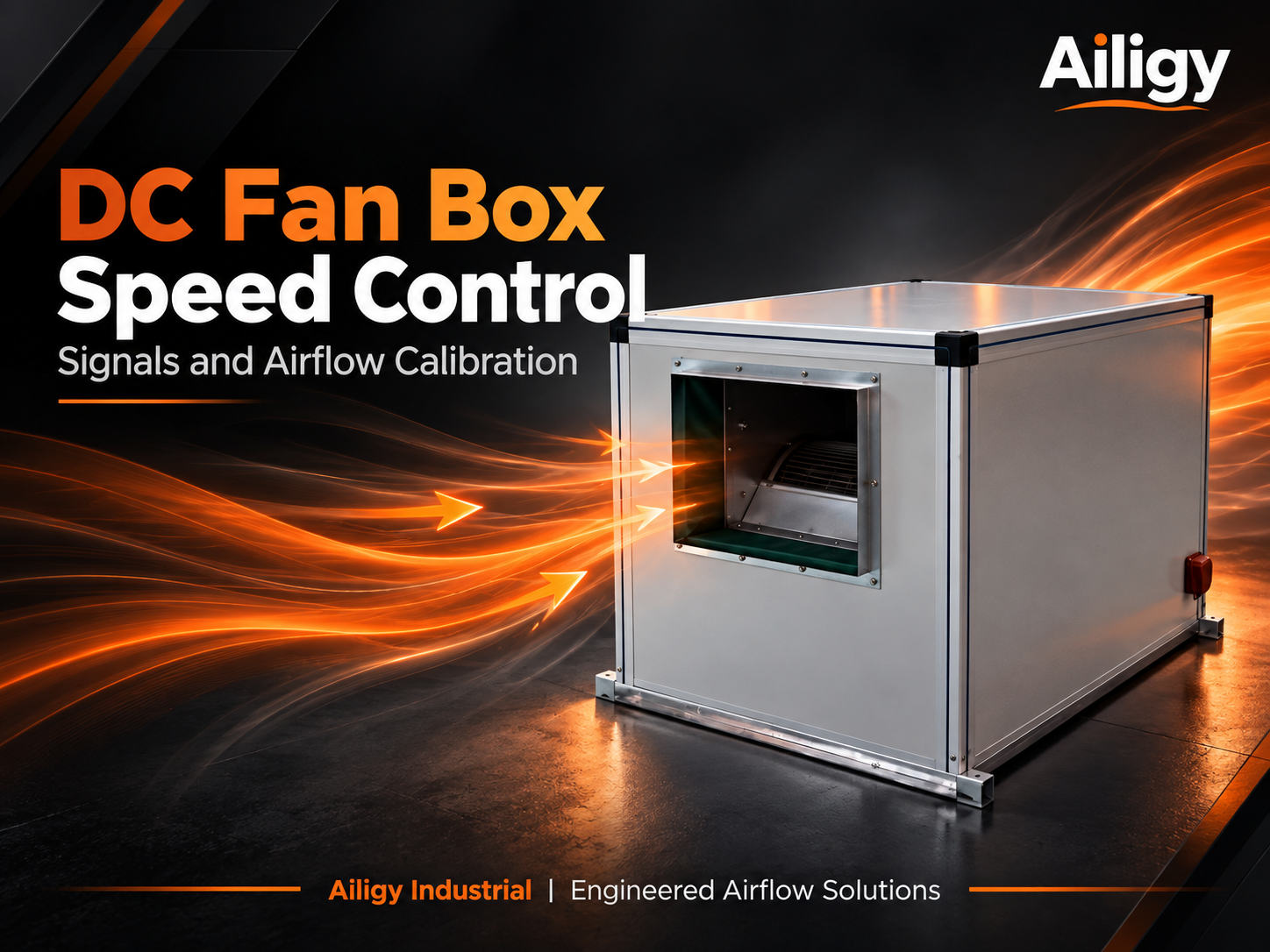 The DC fan chassis uses a matching driver to control the motor speed; whether analog, PWM or communication control can be used depends on the specific electrical interface. It can record control instructions, measured speed, air volume, static pressure, current or input power, and mark the filter status and valve opening. After the speed changes, the system operating point will change along the fan curve and pipeline resistance curve. The controller gives a 50% instruction, which does not mean that the actual air volume must be half of the rated value. Debugging should measure air volume, static pressure and input power at several typical command points to form a corresponding table suitable for the system. The minimum operating air volume should be determined by the required air volume at the end. Actions after fault alarm and disconnection should be agreed before debugging. Operation feedback and fault feedback can be independent signals or obtained through communication.
-
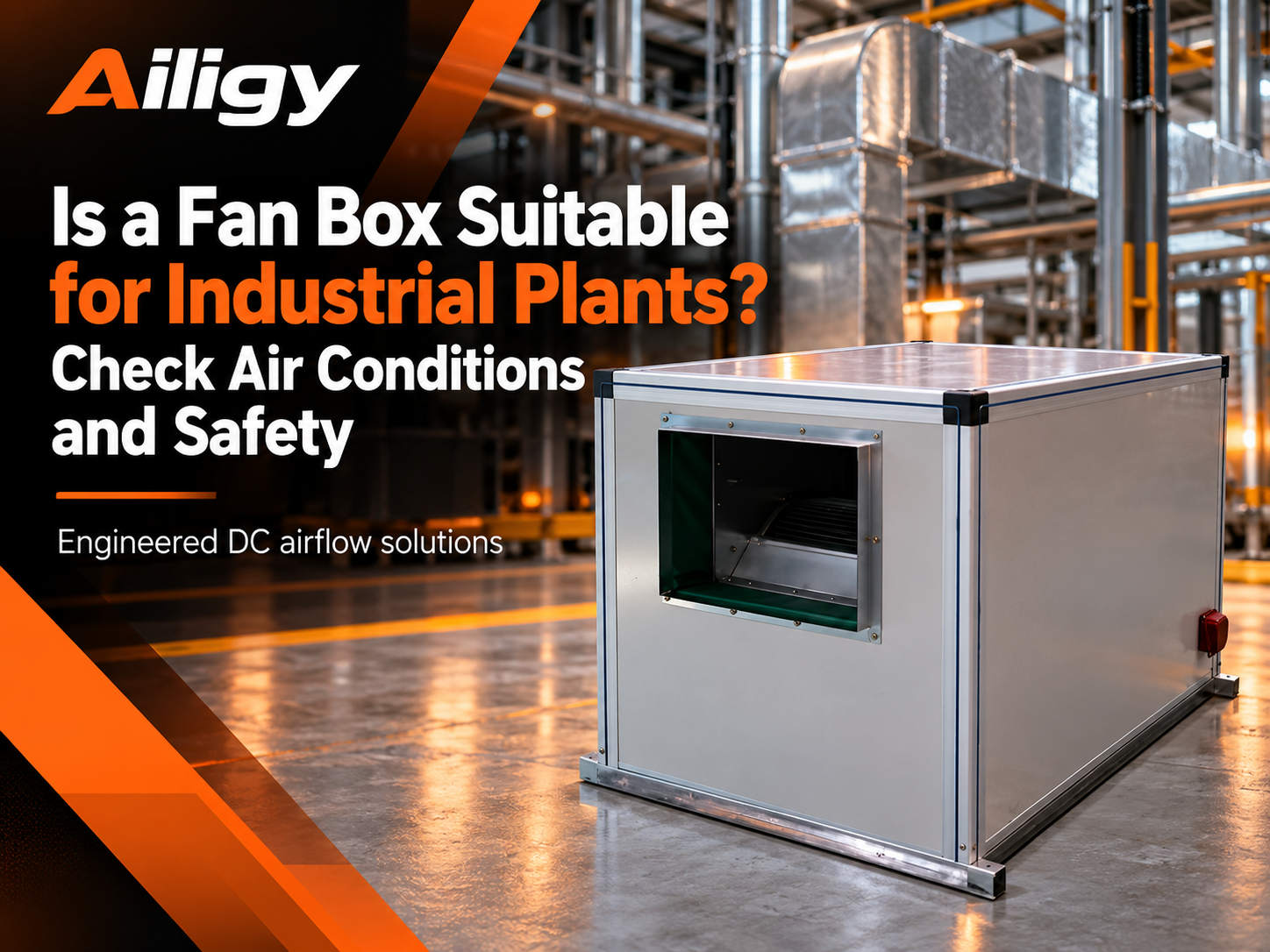 Fan boxes can be used in industrial plants, but the purpose, air medium and safety conditions determine the specific configuration. The air medium is the first parameter to be confirmed. Dust, corrosive, oil mist or combustible gas will change the box material, motor protection and control methods. The fan box can be equipped with a filter and configured with a primary-efficiency, medium-efficiency or high-efficiency filtration section, but the initial resistance and final resistance of the filter must be included in the working point, and the length of the box must be increased accordingly. The resistance of the filter section increases with dust accumulation. The selection should be calculated based on the final resistance. The speed control can adjust the speed according to the pressure difference signal. General ventilation, equipment heat dissipation and process exhaust have different requirements for the fan box, and 'industrial factory' cannot be used as the only selection condition. Special safety requirements such as explosion protection and high temperature require separate confirmation of hazardous area levels and environmental conditions. Aili Industrial has the ability to independently support fans, motors, controls and sheet metal. The installation space, air flow channels and inspection openings of the filter section inside the box can be considered at the design stage. The matching relationship between the fan and filter is checked from the whole machine level.
-
 Clean factories can use fan boxes for air supply and exhaust power, but the filtration efficiency and room pressure difference must be guaranteed by a complete system. The fan box may be used as a circulating air unit, fresh air unit or exhaust unit in a clean air conditioning system. Different locations have different requirements for air volume, static pressure, materials and control methods. The resistance of the filter section is the core variable in selection. The working point should be calculated based on the final resistance, not the initial resistance. The room pressure difference is determined by the supply air, return air, exhaust air and envelope structure. It cannot only look at the air supply volume. Pressure difference control needs to be coordinated at the system level. The box material and surface treatment depend on the installation area and air path. The access space and filter replacement path should be confirmed at the drawing stage. Aili Industrial has the ability to independently support fans, motors, controls and sheet metal. It can calculate working points separately according to the initial resistance and final resistance of the filter section to confirm that the fan can meet the terminal air volume requirements throughout the entire operating cycle, reducing the problems of insufficient estimation of filter section resistance and insufficient speed regulation range coverage.
-
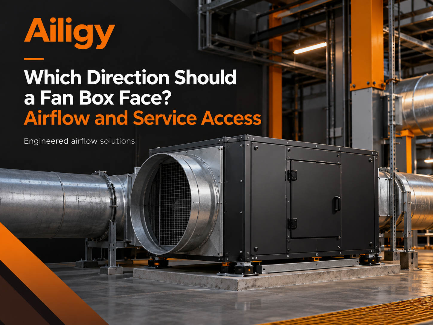 The direction of the fan box involves both air inlet and outlet, as well as maintenance and electrical operation surfaces, and should be confirmed at the construction drawing stage. Before installation, check the direction of the air inlet and outlet according to the system diagram, and do not change it at will just because the direction of the air duct is not easy to connect. The right-hand direction is not a purely cosmetic issue, it affects the position of the motor junction box, the orientation of the access door, the position of the electric control box and the layout of the internal air path. The operating surface should be planned uniformly, and the access door, electric control box, driver and manual turning position should preferably face the same side to facilitate maintenance. Before construction, check the flange size, bolt hole position, soft connection length, shock absorber installation direction and foundation hole position. Before power-on and trial operation, re-confirm the inlet and outlet air direction and impeller rotation. If the direction is not corresponding, stop and adjust immediately. Aili Industrial has the ability to independently support fans, motors, controls and sheet metal. It can mark the wind direction, inspection surface and operating surface during the structure confirmation stage, and adjust the direction of the air outlet, the position of the electric control box and the orientation of the access door according to site conditions, reducing rotation, pipe modification and rework caused by incorrect orientation after the equipment arrives at the site.
-
 The installation location is determined by the wind path, foundation, maintenance, noise and electrical conditions, and needs to be checked with construction drawings. The air path should be as smooth as possible, sharp bends and obstructions should be avoided near the air inlet, and complex elbows should not be directly connected to the air outlet. Inspection channels must be reserved according to specific actions. Opening the access door, extracting the motor, replacing the filter, and wiring the driver each require space in different directions. Changes in location will bring about chain reactions. When hoisting is changed to the floor, a large computer room is changed to a small computer room, or a non-sensitive area is changed to a sensitive area, the foundation and vibration reduction must be re-examined. Measuring points should be reserved in advance, and the pressure measuring hole and air volume measurement section should be selected on a straight pipe section with stable air flow. Noise and vibration transmission must be evaluated. Vibration reduction and silencing cannot replace reasonable air path layout. Aili Industrial has the ability to independently support fans, motors, controls and sheet metal. It can adjust the direction of the air outlet, the position of the inspection surface and the orientation of the control box according to the installation space and maintenance conditions of the project site, reducing on-site rework caused by incorrect orientation and mismatched interfaces after the equipment arrives at the site.
-
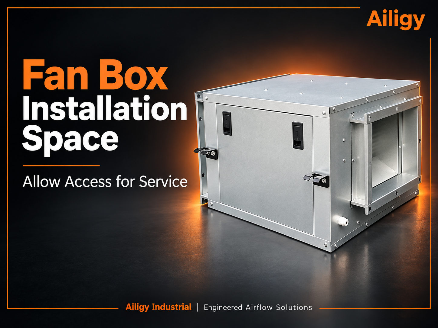 There is no unified figure for the installation clearance of the fan box. It should be determined based on the opening of the access door, the extraction of components, the air duct take-over and the lifting path. It is not advisable to just write 'reserve space for maintenance around the perimeter'. The opening arc of the access door, the extraction direction of the fan or motor, the operating surface of the electric control box and the disassembly position of the soft connection of the air duct should be marked on the equipment diagram. Just because the equipment can be placed in the computer room does not mean that it can be maintained. The access door cannot be opened, the motor cannot be pulled out, and the filter cannot be replaced. These are common problems. The headroom can be divided into four categories: access door opening space, component extraction space, air duct take-over space and personnel operation space. The stacked map of the machine room should check the locations of beams, columns, bridges, water pipes, fire protection facilities and other equipment, focusing on whether the maintenance action space is occupied. For hoisting projects, the transportation path and lifting points should also be checked. Do not wait until the crew arrives to discover that there is insufficient turning or lifting space. The headroom is ultimately determined based on the actual appearance and maintenance methods of the corresponding model. It is not recommended to directly apply the reserved values of other items.
-
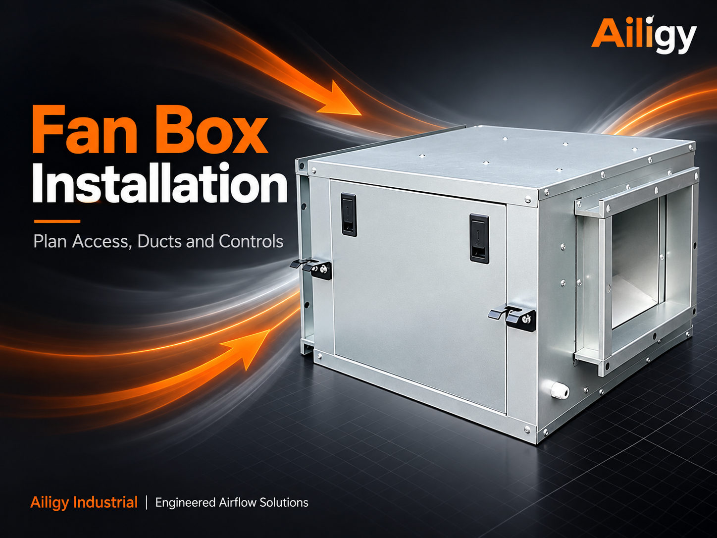 Before installing the fan box, you should check the drawings, equipment wind direction, foundation and vibration reduction, air duct interface, power supply control, and maintenance and hoisting space. The appearance interface, air duct air direction and power control can be confirmed by the equipment, HVAC and electrical parties respectively. If there is friction or abnormal vibration in the impeller during trial operation, the machine should be stopped to find out the cause, and the operation cannot be continued by just increasing or decreasing the speed. Only after the baseline measurement is completed will comparable data be available for subsequent maintenance. The preparation work is divided into four stages: before arrival, after unpacking, during installation, and before powering on. Align the drawings and site conditions before arrival, check the nameplate and random information after unpacking, confirm the air duct, vibration reduction and maintenance space during installation, and check electrical, grounding and control signals before powering on. Just because the equipment can be placed in the computer room does not mean that it can be maintained. The access door cannot be opened, the motor cannot be pulled out, and the filter cannot be replaced. These are common problems.
-
 If the air pressure is too high, it should be judged based on the air volume and segmented pressure difference. First, locate the abnormal resistance of the valve or filter. High pressure does not necessarily mean sufficient air supply. When the downstream valve is closed or the filter is clogged, the static pressure near the fan may increase, but the air volume at the end will be insufficient. Segmented pressure measurement can locate abnormal resistance, record the static pressure at the outlet of the fan box, before and after the filter section, key elbows and the farthest end, and compare the pressure differences in each section. Confirm the terminal demand before adjustment. If the speed is set too high, the speed can be gradually reduced. If the high pressure comes from valve throttling or filter blockage, abnormal components should be dealt with first. Comparison with the original working point is meaningful. The debugging baseline should include static pressure at each measuring point, filter status, valve opening and fan speed. Aili Industrial has the ability to independently support fans, motors, controls and sheet metal. The complete machine test data can be provided according to project working conditions, including external static pressure and power under specified air volume, as a reference for on-site debugging and later maintenance. After the system resistance changes, the working point should be recalculated instead of repeatedly adjusting the valve.
-
 If the air volume is too large, it is necessary to distinguish between the total air volume and the branch problems, and give priority to adjusting the speed and balance according to the actual working point. If the air volume at a certain terminal is too large, it may be due to branch balance imbalance. If the total air volume is too large, it may be due to the fan selection being too large, the system resistance being lower than the design value, or the speed setting being too high. When processing, the speed regulation strategy is given priority to reduce the rotation speed on the premise of meeting the most unfavorable terminal air volume and pressure difference, rather than relying on valve throttling for a long time. The inspection is carried out in order: confirm the measurement method and measuring points, compare the air volume of each branch, check the rotation speed and set value, review whether the system resistance is lower than the design value, and verify the terminal after adjustment. After the design is changed, the working points must be rechecked. Reducing the filter section, shortening the air duct or changing the valve opening during construction will affect the system resistance. Aili Industrial has the ability to independently support fans, motors, controls and sheet metal. It can discuss the speed adjustment plan based on the current air volume, external static pressure and input power. At the same time, it can check whether the motor and driver support the new operating point, so that the whole machine plan can be rechecked based on the original design.
-
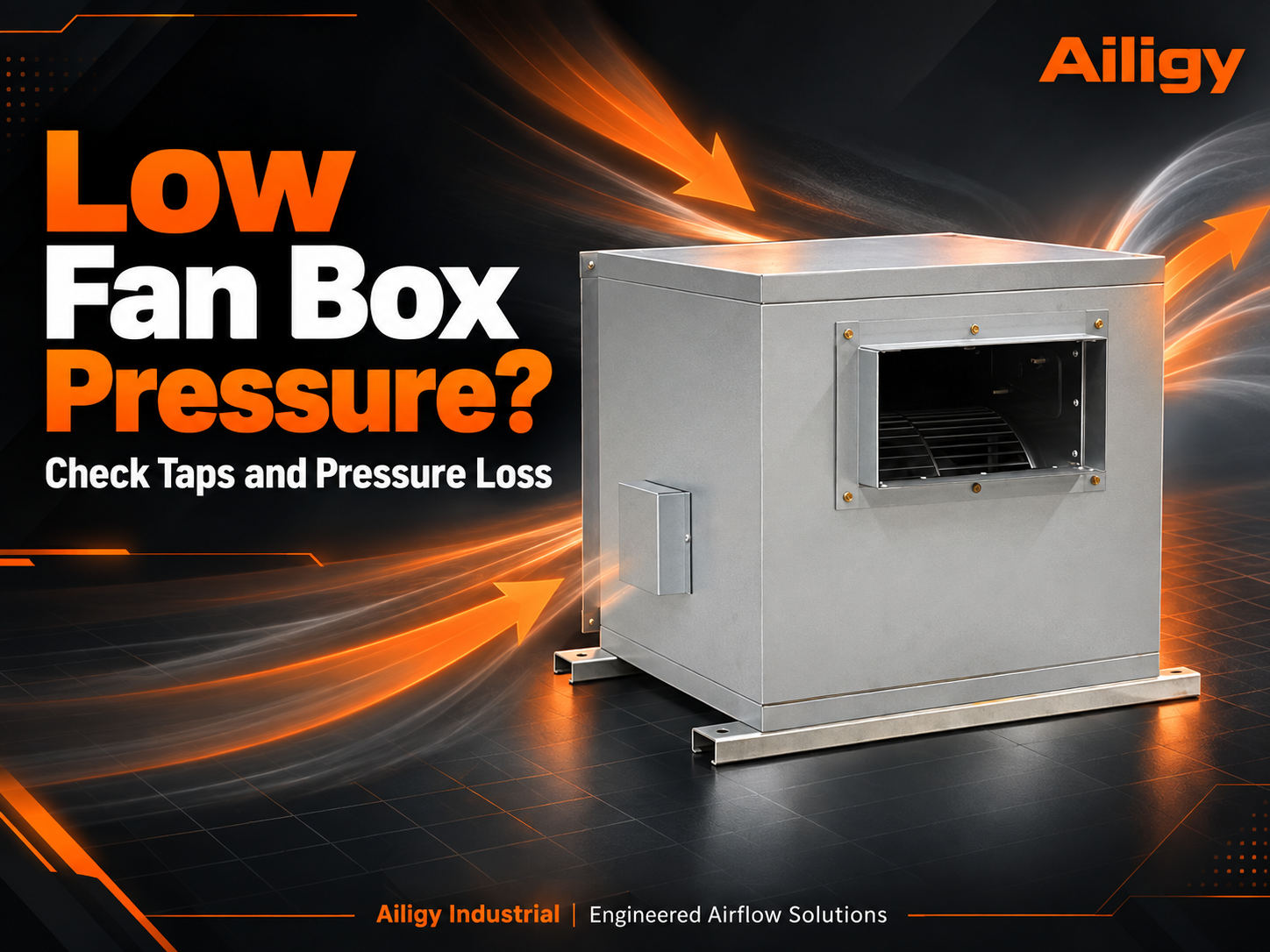 When troubleshooting insufficient air pressure, first distinguish the static pressure at the fan outlet and the external static pressure that can be used to overcome external pipeline resistance, and then check the measuring points, rotation speed and air duct pressure loss. The static pressure at the outlet of the fan box, before and after the filter section, key elbows and the farthest end can be recorded in sequence to compare which section the abnormal pressure loss is concentrated in. Total pressure, static pressure, dynamic pressure and external static pressure have different meanings and different measuring points and cannot be confused. If the instrument range or pressure measurement method is inconsistent, the data cannot be directly subtracted. Make sure your testing methods are consistent before deciding whether to adjust the valve, clean the filter section, or recheck the fan. If a branch or filter section is added to the system later, the original fan chassis curve may no longer cover the new demand. At this time, the working point should be recalculated instead of directly replacing a larger fan. The investigation record should include the location of the measuring point, instrument type, pressure caliber, pressure difference of each section, rotation speed and input power.
-
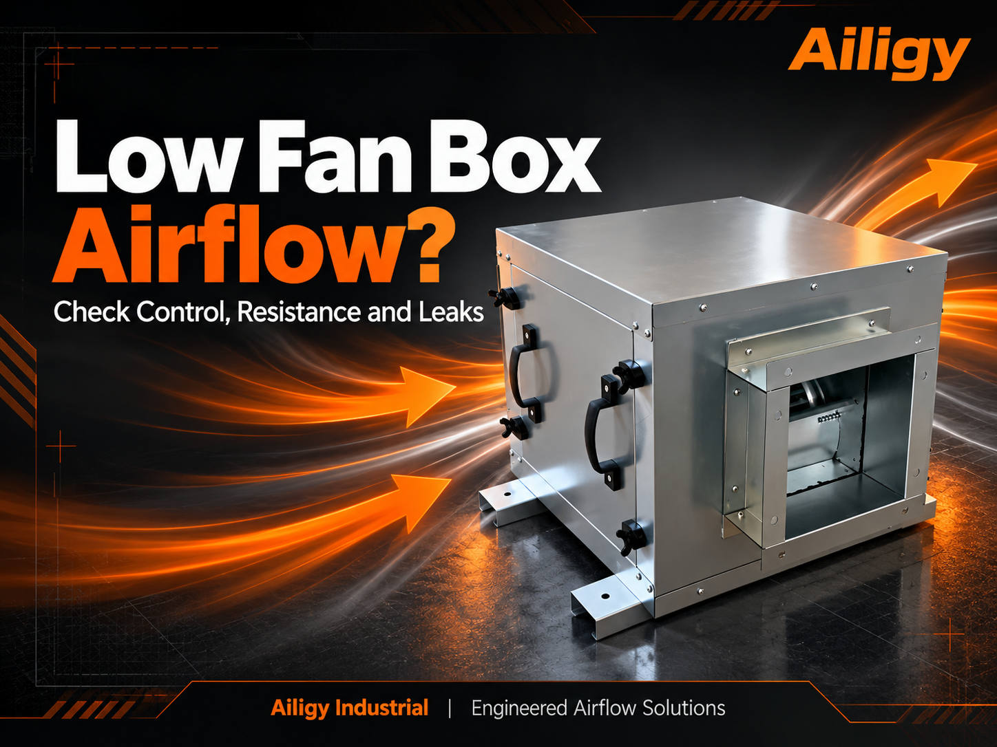 If the air volume of the fan box is insufficient, the measurement working conditions should be confirmed first, and then the speed setting, air inlet and filter section resistance, valve position and air duct leakage should be checked. If the air volume at the fan outlet is normal but the remote air volume is insufficient, give priority to checking air leakage in the pipeline or branch balance; if the air volume at the fan outlet also drops, give priority to checking the rotation speed, air inlet obstruction and overall pressure loss of the system. Failure of the fan box body cannot be determined solely by the wind speed at the end. It is recommended to reproduce the measurement conditions first, then check the control side, then check the resistance side, and finally check the air leakage side. Dust accumulation in the filter section, changes in air valve opening, air duct leakage and branch imbalance are all common causes. Do not increase the speed rashly to avoid increasing noise and power consumption, or covering up blockage and air leakage problems. The inspection record should include the operating mode, rotation speed, control signal, static pressure of each section, valve opening, air volume and input power.
-
 Structural customization can adjust the cabinet and air outlet, but the internal air path, overall machine performance and maintenance conditions need to be checked simultaneously. Structural adjustment is not just about changing the shell. Changing the direction of the air outlet, shrinking the box, and changing the direction of the access door will all affect the way the airflow enters the impeller, the internal channel cross-section, and the pressure loss. One change may affect multiple performances, and air volume, static pressure, noise and motor load may all change. The direction of maintenance is often more critical than the appearance. Being able to enter the machine room does not mean that the equipment can be maintained later. Opening the maintenance door, extracting the motor, and replacing the filter all require corresponding space. The drawings confirm the delivery boundary. The foundation hole position, flange size, wind direction arrow, access door position and sealing method should be clearly stated on the drawings. Aili Industrial has the ability to independently support fans, motors, controls and sheet metal. When the structure is changed, the air path, supports and interfaces can be rechecked from the whole machine level. Sheet metal processing, fan matching and control configuration are coordinated in the same system. The impact of structural changes on performance can be evaluated before manufacturing. Performance and structure must be verified simultaneously. After the structural plan is confirmed, the air volume, external static pressure, input power and noise of the complete machine still need to be tested according to the target working conditions.
-
 Fan box customization should simultaneously define performance, structure, control and maintenance, and implement changes into the complete machine test conditions. The performance boundary is determined first, and the design air volume, external static pressure, noise requirements and operating mode determine the fan and motor selection. The structural list should be drawn on the drawings, including box size, air outlet direction, flange, foundation hole position, access door, electric control box location and filter section installation space. Customization requirements should be written as executable conditions, rather than vague descriptions such as 'low noise, large air volume, and intelligent control.' The control function should use a point table to indicate the signal type, terminal definition and disconnection action. The filter section can be integrated into the fan box, but the initial and final resistance of the filter must be included in the working point, and the length of the box must be increased accordingly. Aili Industrial has the ability to independently support fans, motors, controls and sheet metal. It can consider the installation space of the filter section, air flow channels and access openings during the design stage, and check the matching relationship between the fan and filter from the whole machine level. When delivering, test the performance of the complete machine according to the agreed conditions to avoid only inspecting the appearance without inspecting the operation.
-
 DC fan cabinet customization not only involves the cabinet and air volume, but also includes the driver, speed control signal, interlocking, fault feedback and minimum operating air volume. After the duty mode signal is lost, whether to maintain the current speed, return to the preset speed, or shut down should be determined by the project usage requirements. First, list the actual operating status, such as working shift at full load, night duty, equipment shutdown and fault status. Each status clearly indicates the expected air volume or pressure, allowable speed range and switching conditions. New projects can unify interfaces during the design phase, while renovation projects must first take inventory of original control signals, power supply capacity, flanges and maintenance spaces. Actions when control is abnormal must be confirmed before leaving the factory and reviewed during on-site joint debugging. The control logic should be written as a control point table or logic description and delivered together with the equipment diagram and electrical diagram. Aili Industrial can discuss DC fan box customization solutions based on motor, fan, box and control supporting capabilities. The delivery requirements cover both design and duty conditions, and verify start-stop, speed regulation, alarm and response after disconnection.
-
 The fan box can be customized around the air volume, external static pressure, box size, air outlet direction and control interface, provided that the target working conditions and installation interface are clear. Structural customization will change the internal airflow path, and acceptance cannot be based solely on the box assembly size. Size and performance need to be balanced. Changing the direction of the air outlet, reducing the cross-section or increasing the turns in the box may change the pressure loss and noise. The control interface customization should clearly define the speed control signal type, terminal definition, fault feedback and action after disconnection. The orientation of the access door, motor disassembly and assembly path, vibration reduction method, power supply location and lifting constraints should be determined at the drawing stage. The customized confirmation form should indicate the target working conditions, noise measurement conditions and control actions that need to be verified. When adding filters or modifying air ducts on site later, it can also be used to determine whether the original design boundaries have been exceeded. During acceptance, the air volume, external static pressure, input power, control function and external dimensions of the whole machine should be measured to avoid only inspecting the appearance without inspecting the operating performance.
-
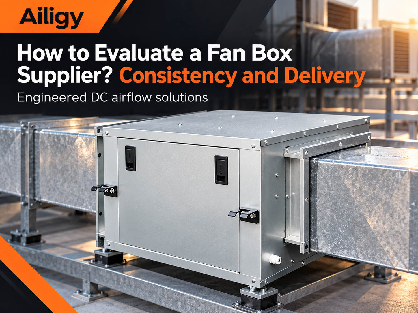 Manufacturing capabilities depend on batch consistency, design version management, complete machine testing and maintainable delivery materials. The qualification of the prototype is only the starting point. For the same model in different batches, the fans, motors, controllers, box openings and assembly requirements should be consistent with those of the confirmed prototype. Batch projects should be based on key component models, assembly directions, air outlet sizes and control program versions. Component adjustments need to be evaluated for their impact on overall machine performance and spare parts. Non-standard projects require version control, and drawings, material lists, production instructions and test conditions must be updated simultaneously after changes. Delivery materials should include electrical wiring diagrams, control instructions, parts lists, factory records and debugging baselines. Multiple equipment should have clear model uniformity and spare parts compatibility range. Aili Industrial has independent supporting capabilities in motors, fans, controls and sheet metal structures. Key components are produced or matched in the same system. The specifications, interfaces and assembly requirements between batches are easier to unify. The test data of the whole machine corresponds to the final delivery configuration, which provides a basis for consistency control of batch projects.
-
 What capabilities should a fan box manufacturer have? Look at the closed loop from design to testingWhen selecting a manufacturer, you should review whether the work points, drawings, quality processes and complete machine test data are consistent. When evaluating a fan box manufacturer, it’s not about the size of the factory, but whether it can translate requirements into working points, implement changes into drawings, provide traceable test data for the entire machine, and deliver usable maintenance data. The ability to select working points is reflected in the ability to proactively inquire about system resistance, filter status, operating period and power supply conditions, and convert them into verifiable working points. Change management depends on drawing version control and whether the fan matching is rechecked after the change. The test record should indicate the air volume, external static pressure, rotation speed and filter status, rather than just 'passed'. Delivery materials should include electrical wiring diagrams, terminal definitions, drive parameter tables, fault code descriptions, spare parts lists and debugging baselines. Aili Industrial has the ability to independently support fans, motors, controls and sheet metal. Working point analysis, structural design, motor matching and complete machine testing are completed in the same system. The complete machine test data corresponds to the final delivery configuration.
-
 When purchasing a DC fan chassis, you should focus on checking the matching of the motor and driver, power under common operating conditions, control compatibility and subsequent maintenance information. Fault diagnosis, spare parts identification and wiring information for DC drives and control boards should be delivered with the equipment. If the manufacturer provides an energy saving comparison, it should be confirmed whether the old and new equipment are measured under the same terminal air volume, filtration status and operating hours. A single percentage that deviates from these conditions cannot be used for project budgeting. The control details determine whether it can be accessed. The speed control signal range, communication protocol, fault output, protection strategy and driver heat dissipation requirements need to correspond to the on-site control cabinet one by one. Later maintenance is also a procurement cost. If there are multiple devices in the project, it is recommended to agree on a unified model and spare parts compatibility range. When purchasing, the driver, wiring data, performance records, drawing confirmation and debugging cooperation should be included in the list to facilitate comparison of the supplier's actual delivery capabilities.
-
 When selecting a fan box manufacturer, you should check performance test conditions, fan motor matching, drawing response, quality control and debugging support. Drawing version control, air outlet size confirmation, complete machine testing and delivery documents after assembly will all affect the final effect of the project. The supplier should be able to clarify the external static pressure corresponding to the air volume, provide curves or test data consistent with the requirements, and explain the measurement conditions of noise and power. Only the 'maximum air volume' and motor rated power are given, and it is impossible to judge how the equipment will operate after it is installed in the system. The quotation should clearly distinguish whether it includes the driver, vibration damping parts, control accessories and on-site debugging. Prices in different ranges are not comparable. The customization process depends on whether the drawings and technical list are implemented, and whether the control interface is clearly defined. Debugging support, spare parts supply and model unification are also important aspects to evaluate the manufacturer's delivery capabilities. Being able to match requirements, drawings and test data is more valuable than a general discussion of the manufacturer's scale.
What information should be prepared before selecting a fan box?
The fan box must work in the actual air path. Providing the following conditions is more helpful in determining the equipment configuration than just reporting a box size or motor power.
System purpose
Air supply, exhaust, or as a supporting fan section for air-conditioning boxes and equipment
Operation control
On-site power supply, start and stop methods, speed control signals, and operating periods
Installation conditions
The available space of the box, the direction of the air inlet and outlet, the interface size, and the maintenance location
Performance requirements
Design air volume, corresponding static pressure, and common operating conditions
For existing equipment renovation projects, the original equipment nameplate, on-site photos, air duct connection methods, and available air volume, pressure, and power records should also be supplemented. If some parameters have not been measured yet, you can first indicate 'to be reviewed on site' to avoid taking the estimated value as a definite basis for selection.
Why choose Aili industrial fan chassis?
The actual performance of the fan box depends on whether the fan, motor, box and control method can cooperate at the same operating point. Aili Industrial carries out product matching around these links, and can discuss configuration plans based on the air volume, static pressure, installation interface and operation requirements of the project.
Selection based on the working point: Check the target air volume and the corresponding static pressure together, and pay attention to common working conditions, instead of determining the model only based on the maximum air volume or motor rated power.
Cooperate with new construction and renovation projects: For new systems, the fan box configuration can be determined according to design conditions; for existing equipment modifications, the original box space, air path, power supply and control interface must be checked first, and then whether the DC fan box is suitable.
Implement customization requirements into drawings: requirements such as the direction of the air inlet and outlet, box size, access surface and control interface should be confirmed together with the work point to facilitate manufacturing, on-site installation and subsequent maintenance.
Let the delivery conditions be verified: Air volume, pressure, power, control functions and test conditions are clearly defined during project communication, so that procurement, debugging and acceptance personnel can check the equipment based on the same set of information.
Aili Industrial can check the applicable conditions of standard configuration or customized solutions accordingly.

Contact us now
