
Number of views: 2650 Author: Aili Industry Release time: 2026-09-28 Source: Ai Li Industrial
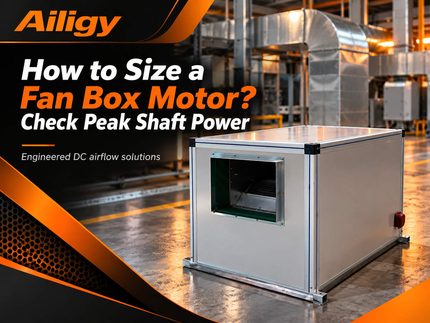
Let me first talk about a situation that is often encountered on site. The air volume of the fan box of a certain project was not enough. Party A's first reaction was 'the motor power is small, change it to a larger motor'. As a result, the motor was replaced with a larger one, but the air volume was still not enough. Because the problem is not with the motor at all, but with the system resistance exceeding the original design, and the fan operating point has deviated. No matter how powerful the motor is, the impeller can only provide so much pressure at this speed, and replacing the motor cannot solve the problem.
How to determine the motor power must be calculated based on the fan curve and shaft power, rather than deciding based on the size of the box or 'how big someone else has it.'
The first step to determine the motor power is to clearly define the design air volume and corresponding external static pressure. These two parameters form the operating point. Find this point on the fan performance curve and read the corresponding shaft power.
Shaft power is the actual mechanical power consumed by the impeller at the target operating point. It is related to air volume, pressure, fan efficiency, and transmission efficiency. The same fan has different shaft power at different operating points. As the air volume increases or the system resistance increases, the shaft power will change.
After the shaft power is found, the rated power of the motor should be greater than it, with a reasonable margin left. The bigger the margin, the better. If the margin is too small, the motor may be overloaded if the filter accumulates dust, the air duct leaks, or the system resistance increases; if the margin is too large, the motor will run in the low-load zone for a long time, and the efficiency and power factor will decrease, which will increase operating costs.
How much margin should be left depends on the degree to which the system resistance can be expected to change. If the system has a filter, and the filter collects dust, then the shaft power should be calculated based on the pressure difference allowed before maintenance, rather than the clean state. From the initial resistance to the final resistance of the filter, the system resistance may increase by tens to hundreds of Pa, the fan working point will move, and the shaft power will also change accordingly.
If the system damper needs to be adjusted frequently, or the branch will be opened at different times, the shaft power changes under these operating conditions should also be considered. The most unfavorable working condition may not be the one with the largest air volume, but the point with the highest system resistance and the heaviest fan load.
Generally speaking, it is a common practice to add a 10% to 20% margin to the shaft power. But this is not a fixed formula and it depends on the project circumstances. If the system resistance changes little, the margin can be smaller; if the filter resistance changes in a large range, or the site conditions are uncertain, the margin needs to be more sufficient.
Many people think that motor selection only depends on the maximum air volume working condition. In fact, the worst case scenario may be another point.
Give an example. The design air volume of a certain system is 10000m³/h, which corresponds to an external static pressure of 600Pa and a shaft power of 3.2kW. However, after the filter accumulated dust, the resistance increased to 900Pa, the fan operating point moved in the direction of small air volume, the air volume dropped to 8500m³/h, and the shaft power increased to 3.6kW instead. If the motor is selected only according to the design working conditions, it may be overloaded after running for a period of time.
There is another situation: the system has multiple branches. When some branches are closed, the air volume of other branches increases, the system resistance curve changes, and the shaft power may also increase. These conditions should be checked during selection.
Therefore, motor power calibration cannot only count one point. The impeller load and motor current should be checked within the expected operating range to confirm that the motor will not be overloaded throughout the operable range.
Two concepts need to be distinguished here. The rated power of the motor is an equipment capacity parameter, which indicates the upper limit of the mechanical power that the motor can continuously output under standard working conditions. The input power of the whole machine is the actual power consumption of the fan box under specific working conditions, which changes with the working point.
It is a common misunderstanding to calculate the rated power of the motor as power consumption, or to think that choosing a higher power will solve the problem of insufficient air volume. If the air volume is insufficient, you should first check the operating point and system resistance instead of blindly increasing the motor. On the other hand, choosing a large motor power does not mean that the operation consumes electricity. The actual power consumption depends on the working point and operating time.
In addition to shaft power and margin, motor selection also depends on the starting method and operating system.
For projects that frequently start and stop on site, the starting current, number of starts and stops, and protective devices must be checked. Just because the rated power of the motor meets the requirements does not mean that unlimited starts and stops are allowed. The current at each start may be several times the rated current, and frequent starts will cause the motor temperature rise to increase. The procurement documents should indicate the number of starts and stops per day, the duration of each operation and whether hot starts are allowed.
For long-term continuous operation projects, attention should be paid to motor temperature rise, insulation level and bearing life. When the motor is running near the rated point, the temperature rise is controllable, but if it runs at low speed for a long time, the cooling effect of the built-in fan will decrease, and the temperature rise may increase instead. When using DC speed regulation or variable frequency speed regulation, the motor needs to confirm whether it is allowed to run continuously in the low speed zone. If necessary, use an independent fan for forced cooling.
In situations where the ambient temperature is high, the altitude is high, or the installation space is poorly ventilated, the motor needs to be derated. The same motor may have completely different temperature rises when installed in a well-ventilated machine room or in a closed mezzanine. These conditions should be confirmed during the selection stage. Do not wait until the equipment arrives to discover insufficient heat dissipation.
If the project adopts a DC speed regulation scheme, after the motor power is determined, the driver current capacity, heat dissipation conditions and protection parameters must also be checked. If the drive capacity is insufficient, the motor cannot output rated torque; if the drive dissipates insufficient heat, it may overheat, reduce frequency, or shut down.
The terminal definitions of different drives may be different. Please check with the electrical diagram and terminal description before on-site wiring. The speed adjustment range of the DC fan box should cover the design working conditions and common working conditions. The minimum operating air volume is determined by the terminal demand, not by the minimum speed of the drive.
The motor power is not selected in isolation, it must be matched with the impeller, driver, and box structure. The impeller does not correspond to the torque characteristics of the motor, the driver parameters do not match the fan curve, and the air path loss inside the box is too large, which will cause the motor to operate in a state that deviates from the high efficiency zone. Aili Industrial has independent matching capabilities in fans, motors, controls and sheet metal structures. It can check the impeller, motor, driver and box at the same working point, calculate the motor capacity based on the shaft power, and confirm the margin, temperature rise and starting conditions at the same time, instead of simply applying based on box size or experience value.
If the system end configurationFor HEPA/ULPA high-efficiency filters , the initial resistance and resistance at the end of use of the filter should be included in the calculation of shaft power. When the process requirements are higher, it can be evaluatedDoes the ULPA ultra-high efficiency filter meet the requirements? Clean room ceiling air supply is comparableFFU fan filter unit ; centralized management of multiple devices can be matchedThe FFU computer group control system realizes zone speed regulation and status monitoring. Protection of single process equipment can be consideredEquipment-side fan filter unit (EFU) . The final filtered air supply at the end of the air duct can beHigh-efficiency air supply outlet (HEPA BOX)。
Specific structure and configuration options can be found inIt is confirmed in the fan box product catalog that non-standard projects should provide equipment or machine room drawings, and then shape them based on the determined working points and on-site interfaces.


