
Number of views: 4064 Author: Aili Industry Release time: 2026-09-28 Source: Ai Li Industrial
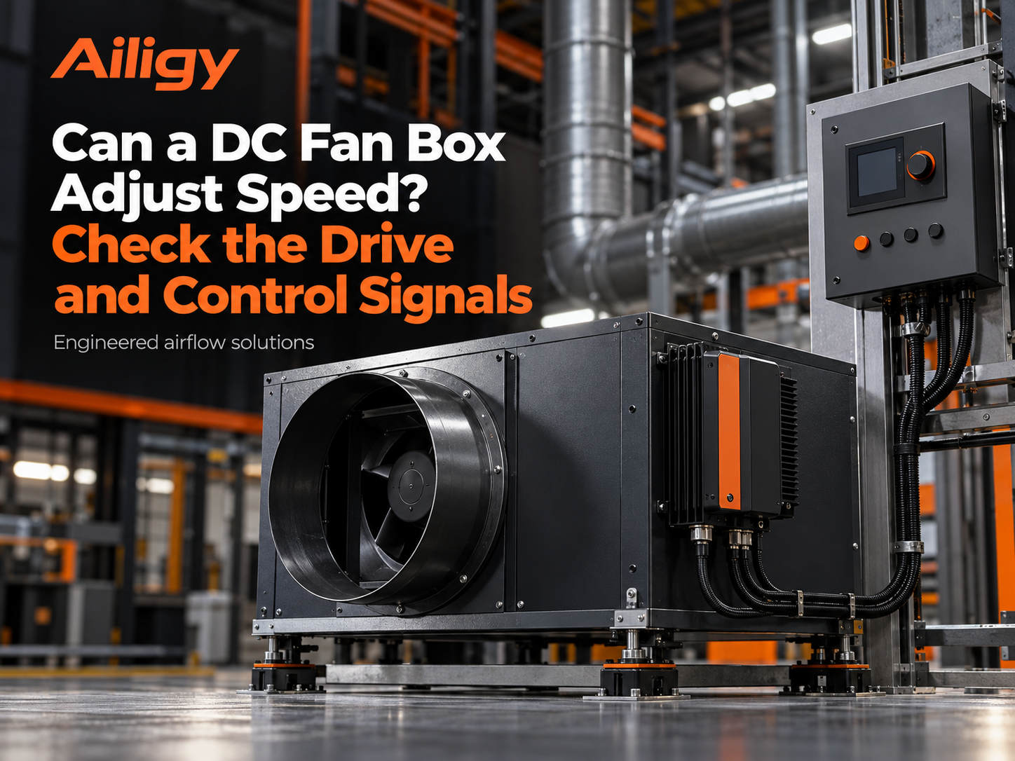
Direct answer: The DC fan box can adjust the speed, but only if the driver can receive the control signal provided on site, and the motor, fan and driver match as a system. Speed adjustment is not just about connecting a potentiometer or giving a 0-10V signal. The signal type, range, terminal definition, minimum operating air volume and fault action all need to be confirmed before ordering. The electrical diagram must be checked before on-site wiring and cannot be guessed based on the terminal names.
DC fan cases usually use EC motors or brushless DC motors, and the speed is controlled by the accompanying driver. The driver receives power supply and control instructions and outputs corresponding voltage or current to drive the motor. The motor itself is just an actuator. How fast it can be adjusted, how low it can be adjusted, and whether it can receive a certain signal depends on the configuration of the driver.
There is a common misunderstanding here: it is believed that 'the speed of a DC motor can be adjusted by connecting it to a DC power supply'. In fact, EC motors have built-in rectification and control modules and can run directly connected to AC power supply, but the speed adjustment needs to be through the control terminals of the driver. Traditional DC motors require an external driver or speed controller, and the wiring method is different. When making a project inquiry, it should be clear which power solution is used, and cannot just write 'DC fan box'.
The matching of the driver and motor also affects the speed range. The rated speed, torque characteristics, insulation level and cooling method of the motor determine its usable range at low and high speeds. The driver's current capacity, control algorithm and protection parameters determine whether it can cover this range. When the two do not match, low-speed weakness, high-speed overcurrent, or excessive temperature rise may occur.
There are usually three types of signals given by on-site control systems.
Analog signal. 0-10V voltage or 4-20mA current directly corresponds to the speed command. This signal is widely used in building automation and industrial control systems and has simple wiring. However, different drives may have different definitions of analog quantities: some 0V corresponds to shutdown and 10V corresponds to full speed; some 2V corresponds to the lowest speed and 10V corresponds to full speed. Below 2V is regarded as a shutdown signal; some have disconnection detection and automatically slow down or stop when the signal is lower than a certain threshold. Before on-site wiring, check the electrical diagram and terminal description, not just the terminal number.
PWM signal. The speed command is transmitted through the duty cycle of the square wave. A duty cycle of 100% corresponds to full speed, 50% corresponds to approximately half speed, and 20% corresponds to the lowest speed. PWM does not rely on voltage size to control speed, so even if the controller can only output a logic level of 3.3V or 5V, it can deliver continuous speed commands from 0 to 100%. The industry standard PWM frequency is usually 25kHz, which is higher than the upper limit of human hearing, which can avoid audible noise during speed adjustment. When purchasing, you should confirm the level range, frequency and duty cycle effective range of the PWM signal. Some drives require the PWM frequency to be within a specific range. Frequency mismatch may lead to unstable speed regulation or unrecognizability.
Communication control. Send speed commands through RS485 or Modbus protocol, and read operating status, fault alarms and actual speed feedback at the same time. Communication control is suitable for projects that require centralized monitoring or linkage of multiple devices. It is necessary to confirm the protocol type, communication address, baud rate, data bits and verification method. If the project requires the status to be read by the building control system, it should also be clear whether the operation feedback and fault feedback are independent signals or obtained through communication. The action after communication interruption must also be agreed in advance, whether to maintain the current speed, return to the preset value, or stop.
The three signals cannot be mixed based on experience. The same terminal form does not mean the same signal definition. The control chart must be checked before on-site access, and if necessary, use a signal generator to simulate instructions to confirm whether the driver response is correct.
The controller gives a command of 50%, which does not mean that the actual air volume must be half of the rated value. After the rotational speed changes, the system operating point will change along the fan curve and pipeline resistance curve. The air volume is approximately proportional to the rotation speed, but the system resistance will change with the air volume, and the actual working point needs to be repositioned on the curve.
Shaft power is approximately proportional to the cube of rotational speed. The rotational speed drops to 80% of the rated value, and the theoretical shaft power is approximately 51% of the rated value. This is the fundamental reason why speed regulation can save energy, but the actual energy saving depends on the load curve and system resistance characteristics.
During debugging, measurements should be made at several typical command points: control command value, measured speed, air volume, static pressure, current or input power. Also mark the filter status and valve opening. A corresponding table is formed that is suitable for this system and is more valuable than the theoretical curve in the driver manual because it includes the resistance characteristics of the actual air duct and filter section. If the same command occurs later but the air volume decreases, this baseline can help distinguish control failures, rising system resistance and air duct leakage.
The minimum operating air volume should be determined by the required air volume at the end, not by the minimum speed of the drive. If the speed drops too low, the fan may enter an unstable zone or be unable to overcome the resistance of the filter section. For the pressure difference control system, the sensor position and pressure difference target should be confirmed during the commissioning stage to avoid adjusting speed based on only one measuring point, resulting in insufficient air volume in the remote area.
After the duty mode signal is lost, whether to maintain the current speed, return to the preset speed, or shut down should be determined by the project usage requirements. Especially in scenarios with minimum air supply or pressure difference requirements, control failure actions must be confirmed before leaving the factory and reviewed during on-site joint debugging. For example, a clean room needs to maintain positive pressure. If the fan stops after the signal is disconnected, the pressure difference in the room will quickly get out of control. At this time, it should be set to maintain a safe preset speed. If the system has an upper limit for pressure difference, the speed should be reduced or stopped after the line is disconnected to prevent the pressure difference from being too high.
The driver should provide operating status output and fault alarm signals. Fault types typically include overcurrent, overvoltage, undervoltage, overheating, phase loss, and communication interruption. Operation feedback and fault feedback can be independent dry contacts or can be read through communication. The signal type and terminal definition should be clearly defined when purchasing, so that the same point list can be accepted on site.
After the analog signal is disconnected, different drives have different default behaviors. Some automatically increase the speed to full speed, some slow down to the lowest speed, and some stop directly. If the system has minimum air supply requirements, it should not shut down after disconnection, but should be maintained at a safe preset speed. If the system has upper limit requirements for pressure difference, the speed should be reduced or stopped after the line is disconnected. These logics should be written in the control scheme and set in the drive parameters. During debugging, signal disconnection should be simulated to verify whether the actual action meets the requirements.
The DC fan box speed control system will eventually be connected to the on-site control cabinet. The signal type, number of terminals, cable specifications and shielding requirements provided by the control cabinet should be consistent with those on the driver side. Common problems in projects are: the control cabinet has reserved 0-10V output, but the driver only supports PWM; or the control cabinet only has start-stop contacts, but the project requires stepless speed regulation. If these interface problems are not confirmed before ordering, the control cabinet will need to be changed or a conversion module will be added after the equipment arrives.
An available control point table should at least include: signal type, signal range, terminal number, common terminal wiring method, shielding grounding requirements, feedback signal type, fault alarm output method, and action after disconnection. The supplier confirms the driver configuration based on this, and the same point list can be used for wiring and acceptance on site.
The reliability of the speed control system depends on whether the motor, driver and control interface are designed as a system. Aili Industrial has independent matching capabilities for motors, fans and controls. EC motors and drives can match parameters according to the project control point table, and the fan impeller and motor torque characteristics can be checked simultaneously. This kind of internal collaboration from the power end to the control end can reduce the common problems of signal incompatibility, parameter mismatch and lack of protection logic in outsourced assembly solutions. The project only needs to provide the expected working mode, power supply conditions, sensor position and target working point. The driver parameters and terminal definitions can be set according to the point table before leaving the factory. During on-site debugging, the wiring can be directly carried out according to the diagram, reducing on-site modifications.
During acceptance, the speed, air volume, static pressure and input power of each command point should be recorded, and the response after start and stop, speed regulation, alarm and disconnection should be verified. Power figures for test conditions are missing and cannot be used for acceptance. Specific structure and configuration options can be found inIt is confirmed in the fan box product catalog that non-standard projects should provide equipment or machine room drawings, and then shape them based on the determined working points and on-site interfaces.


