
Number of views: 5037 Author: Aili Industry Release time: 2026-09-29 Source: Ai Li Industrial
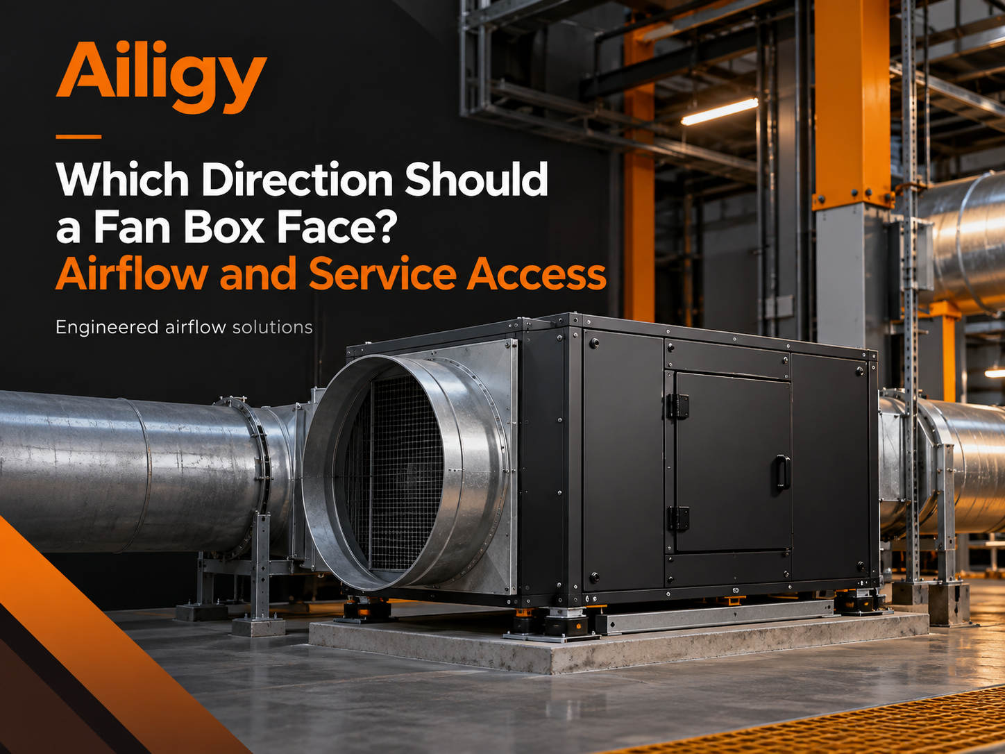
At a project site, the fan box was hoisted in place and the air duct was connected. Everything seemed normal. During debugging, it was found that the air volume was only half of the designed value. I checked it around and found that the motor's steering direction is correct, the speed is correct, and the valve opening is also correct. Finally, it was discovered that the box was installed backwards. The air inlet is connected to the air outlet, the airflow goes in the opposite direction of the impeller, and the fan performance completely deviates from the curve. There is nothing wrong with the device itself, the problem lies in the installation direction.
Direction seems simple, but it actually involves two levels: one is the direction of air flow, and the other is the direction of operation. Both must be aligned so that equipment can work properly and maintenance can proceed smoothly.
The air inlet and outlet directions of the fan box are clearly marked on the equipment diagram. Before installation, check the construction drawings to confirm which section of air duct is connected to the air inlet and which section of air duct is connected to the air outlet.
The air inlet and outlet of some fan cases are fixed at the factory and the directions cannot be interchanged. Some can be adjusted, such as rotating the cabinet or changing the position of the air outlet, but performance may change after adjustment. Don't just swap the air inlets and outlets at will just because the air ducts on site are not easy to connect. After swapping, the impeller may rotate in the opposite direction, causing problems with air volume, air pressure and noise.
For axial flow fan cases, the direction of inlet and outlet air is particularly critical. The airflow direction is reversed and the fan produces almost no air. The centrifugal fan case is relatively tolerant, but reverse air intake will also increase eddy currents and losses, and the efficiency will decrease. Before installation, check the wind direction arrow on the equipment diagram to make sure it is consistent with the system diagram.
Fan boxes of the same model sometimes have left- and right-hand directions. This distinction is not an appearance preference, it affects the position of the motor junction box, the orientation of the access door, the position of the electric control box and the layout of the internal air duct.
For example, a fan chassis is designed with left entry and right exit, the motor junction box is on the left, and the access door is on the right. If the equipment can only be accessed from the right side on site, and the equipment is oriented from the left hand, the access door will face the wall and cannot be opened during maintenance. At this time, it is necessary to explain in advance that the manufacturer should produce the box in the right-hand direction instead of rotating the box 180 degrees after arrival. After rotation, the air duct interface, foundation hole position, and cable path may all be wrong.
There is another situation: there is enough space on site, but the direction of the operating surface and the control cabinet do not match. The equipment can be put down and the air duct can be connected, but the electrical control box faces the corner, making wiring and debugging awkward. This kind of problem can be discovered at the drawing stage. If you wait until installation to pay attention to it, you will have to change the position of the control cabinet or lengthen the cable.
The fan box has several surfaces that need to be operated: access door, electric control box, driver, junction box, and manual turning position. It is best to face these surfaces towards the accessible side to facilitate maintenance personnel's operation.
If the access door faces left and the electric control box faces right, personnel will have to run back and forth on both sides of the equipment during maintenance, which is inefficient and can easily miss inspections. If the driver is installed in a box, the direction of the heat dissipation vent should also be considered and cannot face the wall or heat source.
When multiple devices are installed side by side, operating surface planning is more important. Several fan cabinets share an access channel. The access doors should face the channel uniformly, and the electric control box should also face the channel or a location that is convenient for observation. If one is facing left and the other is facing right, no matter how wide the passage is, it will not be enough.
After the direction is determined, several details need to be reviewed before construction.
The flange size and bolt hole locations must be consistent with the air duct. The direction is correct, but the flange does not match up, so it still needs to be changed. The soft connection must be of appropriate length and cannot be stretched or squeezed. After the direction is adjusted, the soft connection may not be long enough and needs to be prepared in advance.
The installation direction and force of the shock absorber must comply with the design. Some shock absorbers are directional, and the effect will be reduced if installed backwards. The location of foundation holes and embedded parts must also be checked with the equipment drawing. If the direction has changed, the hole positions may not match up.
Special interfaces such as drain outlets, inspection ports, and sensor interfaces also have direction requirements. The drain outlet should be at the lowest point, the inspection port should be easy to operate, and the sensor interface should avoid the air flow disturbance area. These details are marked on the equipment diagram and should be confirmed one by one before installation.
Before powering on for trial operation, re-confirm that the inlet and outlet air directions are consistent with the system diagram. Manually turn the wheel to check the rotation direction of the impeller and confirm that it is consistent with the equipment identification. During the inching test run, observe whether the air flow direction is correct and whether there is any abnormal vibration or noise.
If you find that the direction is wrong, you should stop the machine immediately and make adjustments. You cannot make up for it by increasing the speed or changing the control logic. Wrong direction is an installation problem, not a control problem, and cannot be solved by control means.
Orientation issues are best resolved before manufacturing. The project provides machine room drawings and air duct directions, and the manufacturer produces according to the actual direction. Aili Industrial has independent supporting capabilities in fans, motors, controls and sheet metal structures. It can mark the wind direction, inspection surface and operation surface during the structure confirmation stage, and adjust the direction of the air outlet, the position of the electric control box and the orientation of the access door according to site conditions. This kind of internal coordination from the overall machine structure to the installation direction can reduce the rotation, pipe modification and rework caused by incorrect orientation after the equipment arrives on site. The equipment drawing corresponds to the site conditions, and the construction party installs it according to the same version of the drawing. The orientation problem is solved at the drawing stage.
System end configurationFor HEPA/ULPA high-efficiency filters , the installation direction of the filter may also be required, which should be confirmed according to the equipment label. When the process requirements are higher, it can be evaluatedDoes the ULPA ultra-high efficiency filter meet the requirements? Clean room ceiling air supply is comparableFFU fan filter unit ; centralized management of multiple devices can be matchedThe FFU computer group control system realizes zone speed regulation and status monitoring. Protection of single process equipment can be consideredEquipment-side fan filter unit (EFU) . The final filtered air supply at the end of the air duct can beHigh-efficiency air supply outlet (HEPA BOX)。
Specific structure and configuration options can be found inIt is confirmed in the fan box product catalog that non-standard projects should provide equipment or machine room drawings, and then shape them based on the determined working points and on-site interfaces.


