


Clean air supply at equipment end
Provide filtered clean air to designated locations based on key process areas within the equipment.
Ultra-thin and small size design
Structural matching for production equipment with limited head space, compact internal structure or restricted installation height.
Standard and non-standard customization
It can be configured according to the installation size, target air volume, static pressure, filtration efficiency, material and interface requirements.
Control and system integration
Supports multi-speed speed regulation, zone control, RS485 communication and interface cooperation with equipment control systems.
-
 DC fan cabinets are mainly used for air supply and exhaust systems that need to adjust the air volume on demand. They are especially suitable for projects where the operating period, regional load or the number of equipment turned on will change. Time-sharing operation is the most typical usage scenario. The speed can be switched according to work, duty and other modes to reduce the input power during low load periods. Demand air can also manage regional load changes, but reducing the speed will also change the pressure available, and it must be verified that the most unfavorable end still meets the requirements. New projects can unify control interfaces during the design phase, while renovation projects must first take stock of the original control signals, power supply capacity, and maintenance space. To judge applicability, it is necessary to provide the design air volume, common air volume, corresponding external static pressure, operating period, most unfavorable end demand, power supply conditions, speed control signal type and installation conditions. Aili Industrial can discuss the configuration of the DC fan chassis according to actual working conditions, and the division of labor boundaries with EFU, FFU, high-efficiency air supply vents and other equipment will be clearly defined on the system flow chart.
-
 This article explains the role of the fan box in air supply and exhaust from the system position, and distinguishes between power equipment and terminal filter equipment. The fan box is mainly used to provide air supply and exhaust power for air ducts or equipment, and is suitable for systems that need to overcome the resistance of pipelines and components. Air supply, exhaust and pressurization are three typical uses. Different uses have different selection boundaries. The fan box does not directly define the air cleanliness level. Cleaning projects need to separately determine terminal solutions such as high-efficiency air supply outlets, HEPA/ULPA filters or FFU. To determine whether the purpose is matched, air supply or exhaust, design air volume, external static pressure, air medium, operating time, control method and installation conditions should be provided. Only by knowing the position of the fan box in the entire air path can the box structure, fan curve and maintenance direction be determined.
-
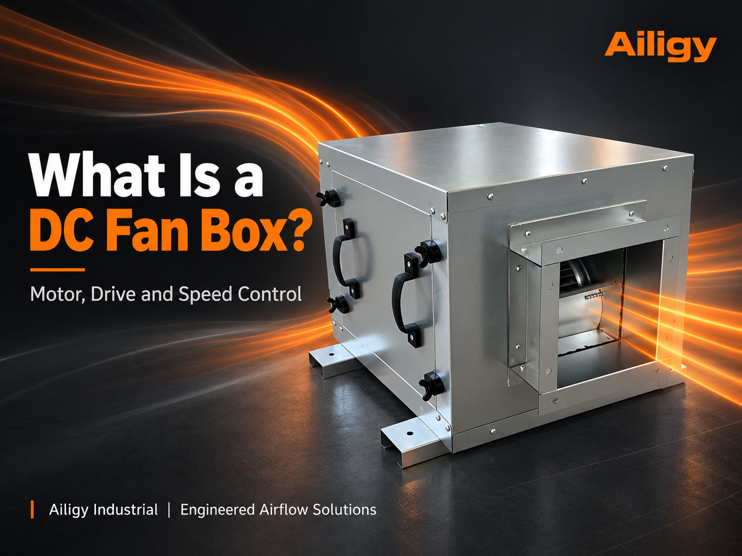 The DC fan box drives the fan with a DC or electronically commutated power system. Only by understanding the cooperation of motors, drives and control signals can you judge whether it is suitable for a new construction or renovation project. The rated power of the motor is used to define the capacity of the motor, and the input power of the fan box is the actual power consumption of the whole machine under specific working conditions. The two are not the same number. When making an inquiry, you should confirm the speed control signal, start and stop methods, fault feedback and minimum operating air volume.
-
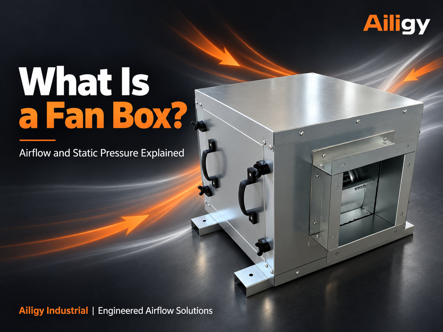 The fan box is a combined device that provides air supply and exhaust power to the air duct or equipment. This article explains its boundaries with filters and FFU, as well as the selection method based on air volume and system resistance. The air volume is sufficient when the same typhoon chassis is connected to a short air duct, but cannot meet the end requirements after being connected to a new filter section and long air duct. This is not necessarily a motor failure.
-
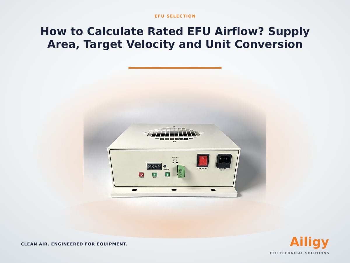 How to calculate EFU rated air volume? Air supply area, target wind speed and unit conversion methodFocusing on 'How to Calculate EFU Rated Air Volume', this article explains the judgment method of effective air supply area, target wind speed, unit conversion, system resistance and fan working point. It also provides prototype records and batch curing points for direct verification by equipment design, procurement and maintenance personnel. Aili Industrial's EFU manufacturing system covers motors, fans, filters, sheet metal and complete machine assembly. The air volume, filter resistance and fan operating point can be checked by model in the same system. When calculating the EFU rated air volume, you can refer to the complete machine and filter supporting instructions provided by Aili Industrial by model.
-
 This article focuses on the setting method of EFU outlet wind speed, and proposes that it should be promoted in the order of cleanliness target, air supply area, target wind speed, air volume inversion and uniformity confirmation. The article explains that the cleanliness target determines the wind speed range, and the air supply area determines the air volume demand, and provides six steps for setting the wind speed, including confirming the cleanliness target, confirming the effective air supply area, determining the target wind speed, inferring the required air volume, matching the fan working point and confirming uniformity. The article also explains the measurement point layout, average calculation and non-uniformity assessment methods for uniformity confirmation, provides wind speed setting references and information required for model selection in different equipment scenarios, and introduces Aili Industrial’s capabilities in fan matching, self-production of filters, structural design and complete machine verification, making it easier for equipment-side projects to complete the setting and acceptance confirmation of EFU outlet wind speed.
-
 EFU size selection should be checked from five aspects: available space of the equipment, target air supply area, air inlet and outlet conditions, installation interface and maintenance path. Just because the shape can be put in does not mean that the air volume, coverage and maintenance requirements are met.
-
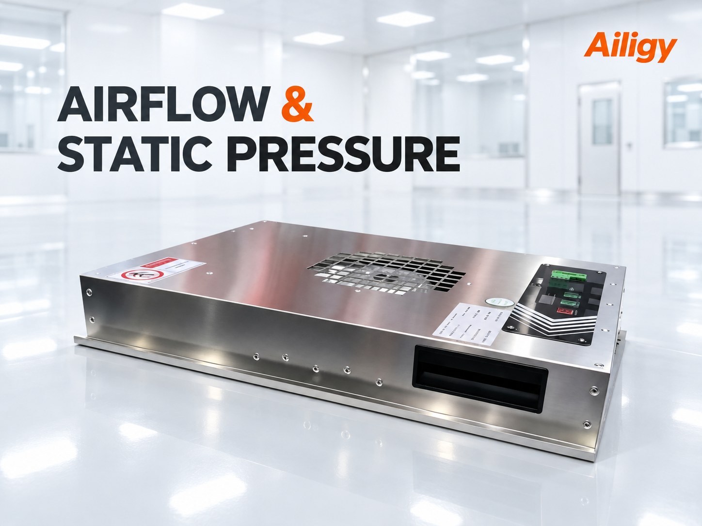 EFU air volume represents the air delivery volume, and static pressure represents the ability to overcome resistance. When selecting the model, you must check both under the same working conditions and explain the filter, rotation speed and installation boundaries to determine the actual working point after installation.
-
 This article focuses on 'How to choose ultra-thin EFU filters' and explains the judgment method of size matching, effective area, resistance, sealing method, replacement direction and complete machine matching. It also provides drawing confirmation, prototype testing and batch curing suggestions for direct verification by equipment design, procurement and maintenance personnel. Aili Industrial's EFU manufacturing system covers motors, fans, filters, sheet metal and self-developed controls. The size, area, resistance and replacement direction of ultra-thin EFU filters can be checked according to equipment drawings in the same system. When selecting ultra-thin EFU filters, you can refer to the instructions provided by Aili Industrial for filter and complete machine matching by model.
-
 This article focuses on the selection method of small-size EFU, and proposes that the four key points of equipment opening, target air volume, filtration area and control interface should be reversely confirmed instead of selecting standard products first. The article explains that the opening of the equipment determines the outer boundary of the box. The air volume needs to be confirmed according to the target area and system resistance. The filtration area directly affects the surface air speed, resistance and filter life. The control interface determines whether it can be linked with the equipment system. It also lists common selection misunderstandings and configurations of different equipment scenarios. direction, and also recommends related product pages such as Aili Industrial small-size EFU, ultra-thin EFU, DC EFU, snap-on EFU, SMT placement machine EFU, anti-static EFU, 86-type controller and customized EFU to facilitate users to further select according to application scenarios.
-
 This article focuses on the application and customization of narrow-body EFU, explaining that narrow-body EFU is mainly suitable for width-limited scenarios such as semiconductor equipment, SMT placement machines, precision inspection equipment, automation equipment, and small clean work units. The article focuses on analyzing the changes in air duct resistance, filter windward surface uniformity and fan operating point after width compression, and gives the confirmation points of filter selection, fan matching, installation design and control linkage, and lists the information required for narrow-body EFU customization. It also recommends related product pages such as Aili Industrial EFU, small size EFU, ultra-thin EFU, DC EFU, snap-in EFU, SMT placement machine EFU, anti-static EFU and 86-type controller to facilitate users to further select according to equipment scenarios.
-
 The 70mm ultra-thin EFU is suitable for equipment-side applications with limited top space, but the selection cannot only confirm the height. It is also necessary to check the air inlet conditions, effective filter area, target air volume, static pressure, uniformity, wiring and maintenance direction.
-
 Low-height EFU is not a simple flattening of conventional structures. To take into account air volume, static pressure and noise, it is necessary to jointly design from the fan working point, inlet space, filter resistance, box stiffness and speed regulation strategy.
-
 This article focuses on 'When does the drop-down EFU need to be customized?' It explains the judgment method of whether customization is needed, structural boundary freezing, technical agreement, sealing structure, prototype verification and acceptance points, and gives the key points of drawing confirmation, prototype testing and batch curing for direct verification by equipment design, procurement and maintenance personnel. Ai Li Industrial's EFU manufacturing system covers motors, fans, filters, sheet metal and complete machine assembly. The structure, sealing and complete machine performance of the detachable EFU can be checked according to the equipment drawings in the same system. When customizing the detachable EFU, you can refer to the structure and performance supporting instructions provided by Ai Li Industrial according to the model.
-
 This article focuses on the customization method of side air inlet EFU, explaining that the side air inlet structure is suitable for scenarios where the top space of the equipment is limited. It emphasizes that the position of the air inlet must first confirm the mechanical shielding, pipeline cables and maintenance channels, then evaluate the changes in air duct resistance caused by the side air inlet, and finally determine the fan working point, box size and equipment interface. The article also provides the matching of filters and fans, the direction of customization for different equipment scenarios, and the information required for project communication. It also recommends relevant product pages such as Aili Industrial EFU, customized EFU, small-size EFU, DC EFU, snap-on EFU, SMT placement machine EFU, anti-static EFU, ultra-thin EFU and 86-type controller, etc., to facilitate users to further select according to application scenarios.
-
 How to design the EFU special air outlet? Air supply range, uniformity and equipment structure matchExplain the structural boundaries, airflow distribution and equipment interface design methods of special air outlets. The EFU design of the special air outlet should be carried out in reverse direction from the target clean area, clarifying the air supply coverage, allowable wind speed, equipment shielding and return air path, and then determining the outlet size and internal flow diversion. Aili Industrial provides non-standard EFU customization and prototype testing.
-
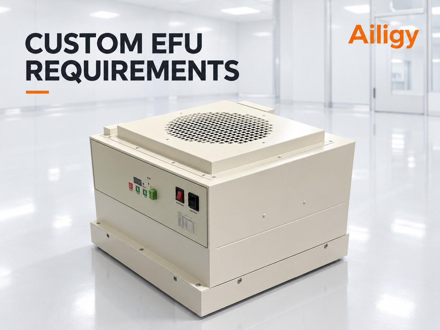 Non-standard EFU customized data should cover equipment space, air supply area, air volume and static pressure, filtration efficiency, power supply control, installation, maintenance and acceptance methods. The more complete the data, the easier it is to detect interference and performance risks during the prototype phase.
-
 Special-shaped EFU is suitable for equipment areas where standard rectangular units cannot be installed, but any avoidance will change the effective space and airflow path. Structural strength, local resistance, sealing and maintenance accessibility need to be controlled simultaneously during design.
-
 This article focuses on the calculation and measurement of EFU surface wind speed. It explains that the basic formula of surface wind speed is the air volume divided by the effective filter area, and provides the air volume unit conversion method. The article focuses on the method of confirming the effective filtration area, including the actual air outlet area of the filter, occupancy of the frame and sealing strips, structural occlusion and the impact of multi-filter configuration. It also gives the measurement point layout principles, covering the measurement plane, number of measurement points, grid layout and interference avoidance. It also introduces the calculation method of arithmetic mean, non-uniformity and relative standard deviation, as well as measurement precautions and acceptance suggestions. The article also lists the information required for surface wind speed calculation, and introduces Aili Industrial's supporting capabilities in fan matching, self-production of filters, structural design and complete machine verification, so as to facilitate the measurement and determination of EFU surface wind speed in equipment-side projects.
-
 This article focuses on the problem of uneven EFU outlet wind speed, explaining that the investigation should be carried out in the order of fan position, filter status, structural obstruction and system resistance. The article analyzes fan position problems such as eccentric installation of the fan, too close to the filter, uneven layout of multiple fans, filter problems such as uneven filter resistance, poor sealing, and mismatched specifications, as well as the impact of obstruction problems such as internal brackets, cable pipelines, and equipment mechanical structures on the wind speed distribution. , and gave corresponding improvement methods and wind speed uniformity acceptance suggestions. It also listed the information required for troubleshooting and introduced Aili Industry's supporting capabilities in fan matching, self-production of filters, structural design and complete machine verification, so as to facilitate equipment-side project positioning and solve the problem of uneven EFU outlet wind speed.
-
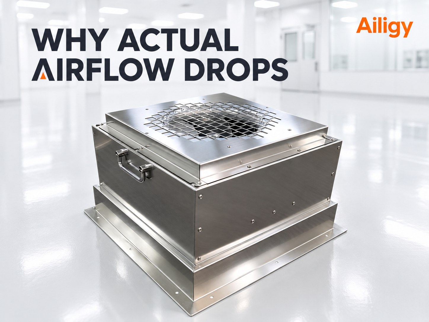 EFU rated air volume must correspond to specific test conditions. After installation, increased system resistance, inlet bias, filter pressure difference, equipment blocking, or changes in speed setting will all shift the actual working point and reduce the air volume.
-
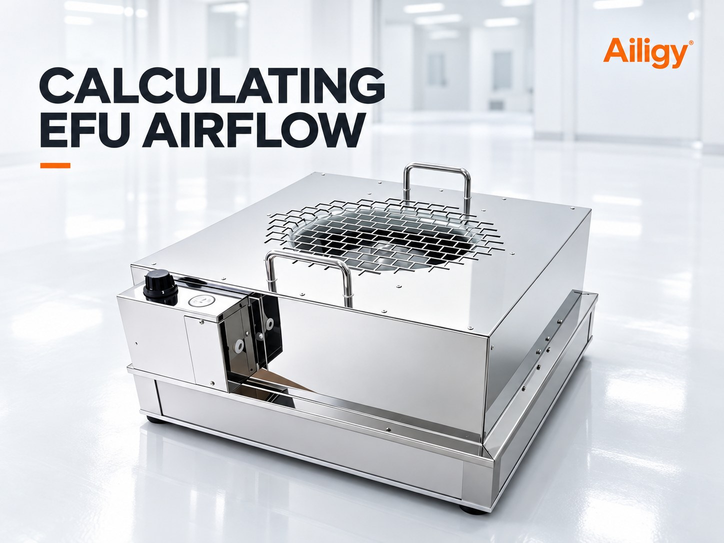 The EFU demand air volume can be calculated based on the effective air supply area and the target average wind speed, but the calculated value is only a starting point. The actual selection also needs to consider the resistance caused by the filter, box, air inlet and outlet, and the internal structure of the equipment.
-
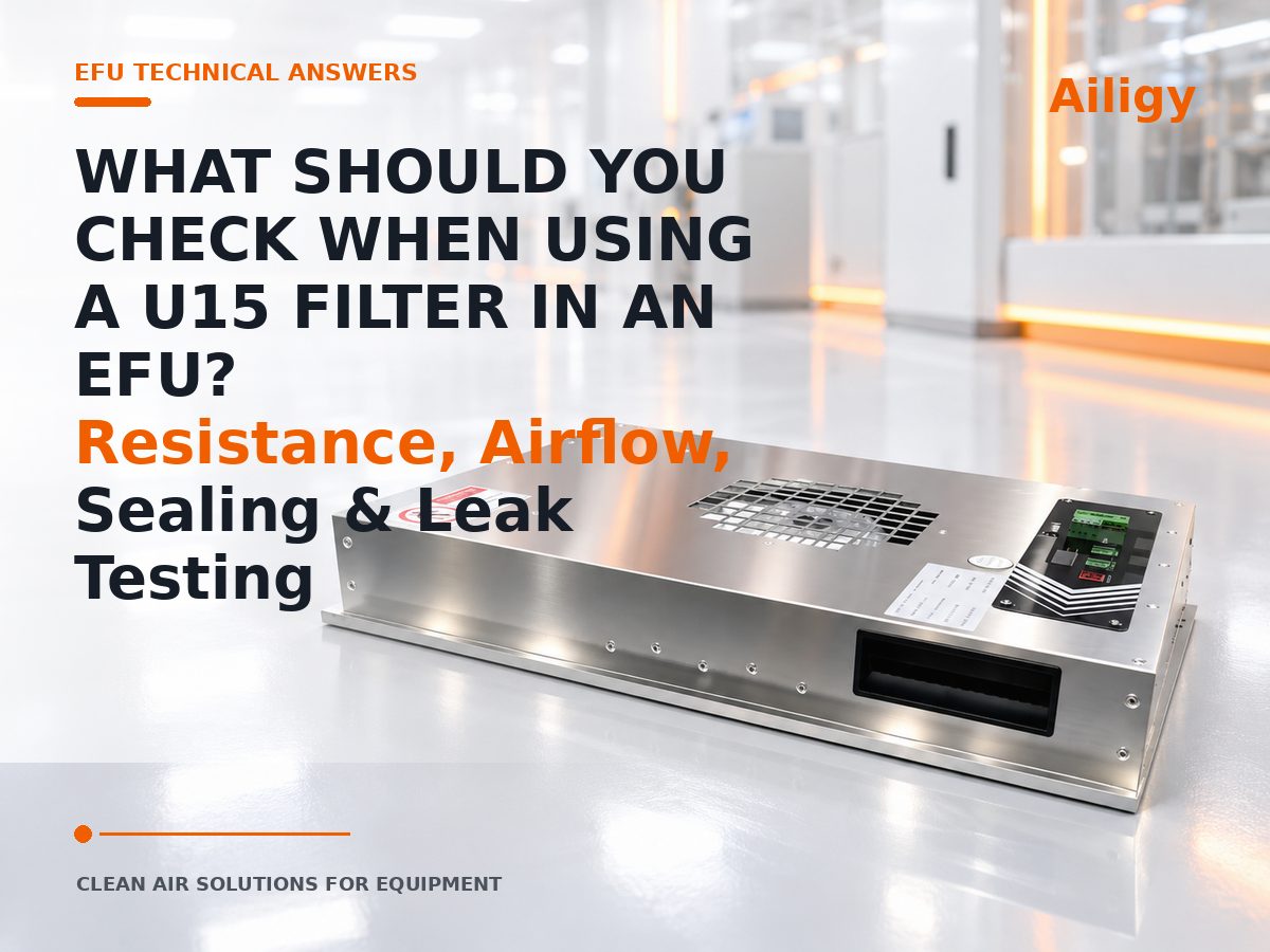 This article focuses on the precautions for configuring U15 filters for EFU. It shows that U15 is a ULPA-level filter, and the initial resistance and final resistance are higher than conventional HEPA. When selecting, the air volume should be reversed according to the target surface wind speed, and the fan operating point should be checked according to the final resistance condition. The article also explains the areas of concern in the sealing structure of the U15 EFU, including the filter and box, the box and mounting surface, the filter frame and the inspection opening, as well as the verification points for scanning and leak detection after the complete machine is assembled. It also lists the parameters required for selection and introduces Aili Industrial’s supporting capabilities in ULPA filters, EC/DC fan matching, sealing structure design and complete machine verification, so as to facilitate the equipment-side project to complete the selection and acceptance confirmation of U15 grade EFU.
-
 This article focuses on the selection and verification of U16 ULPA filters configured with EFU, explaining that U16 filters have higher initial resistance and final resistance characteristics that increase with the dust content. The selection should be based on the target surface wind speed and the total resistance of the system to confirm that the fan can still maintain the target air volume under the final resistance condition, rather than just matching the initial resistance. The article provides the five-step logic of fan matching, the whole machine performance verification method, including surface wind speed measurement, resistance verification, fan working point confirmation and filter leakage detection, as well as a list of parameters required for selection. It also introduces Aili Industrial’s supporting capabilities in ULPA filters, EC/DC fan matching and whole machine verification, which facilitates the equipment-side project to complete the selection and acceptance confirmation of U16 grade EFU.
-
 H13 is the filtration efficiency level, which does not mean that any H13 filter can be directly replaced. EFU selection also needs to match the size, rated air volume, resistance, thickness, sealing method and project detection method.
-
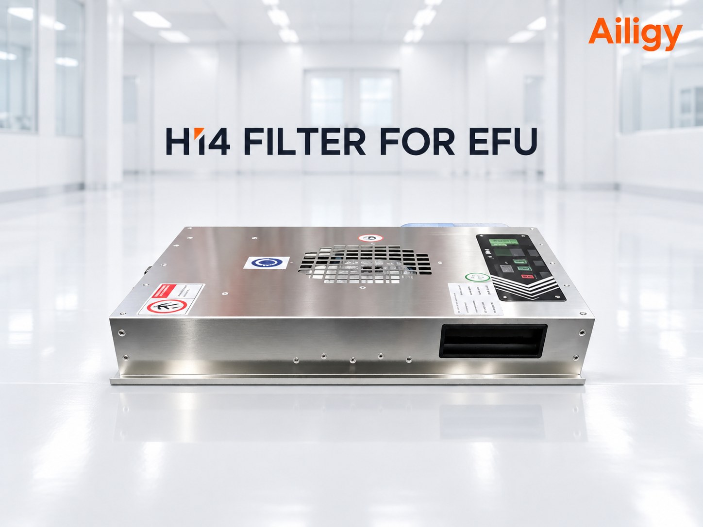 When H14 filters are used in EFU, efficiency, resistance at target air volume, fan residual pressure, filter and box sealing, and leak detection methods should be confirmed at the same time. Simply upgrading H13 to H14 may change the operating point of the entire machine.
-
 This article focuses on 'How to judge abnormal working point of EFU fan' and explains the linkage judgment method of the four parameters of rotation speed, current, static pressure and filter pressure difference. It divides the causes of failure into two categories: system side resistance change and fan side performance change. It also provides the inspection sequence of data comparison → system side → fan side for verification by equipment operation and maintenance and purchasing personnel. The working point parameters of Aili Industrial's 70mm ultra-thin EFU are marked in the confirmation diagram, and the control scheme supports operating data reading and benchmark comparison.
-
 This article focuses on the matching method of EC motors for EFU, and explains the key points of matching from three directions: speed regulation mode, efficiency range and control interface. The article compares the applicable scenarios of potentiometer, 0-10V, PWM and communication speed regulation, explains that the EC motor efficiency needs to be comprehensively evaluated based on the actual operating point, system resistance and operating speed, and lists the interface confirmation contents such as power supply, speed regulation signal, status feedback and communication protocol. The article also explains the collaborative matching relationship between EC motors, fans, and filters, provides scheme references and information required for selection in different equipment scenarios, and introduces Aili Industries’ capabilities in self-production of motors, fan matching, control matching, and complete machine verification, so as to facilitate the confirmation of the EC motor scheme of EFU for equipment-side projects.
-
 This article focuses on the selection comparison of EFU AC motors and DC motors. From the three dimensions of operating mode, speed regulation capability and equipment interface, it is shown that AC motors have a simple structure and are suitable for applications with fixed operating conditions. DC motors and EC motors are convenient for speed regulation, equipment linkage and status monitoring, and are more suitable for scenarios that require on-demand air supply or communication with equipment PLC. The article also compares the interface methods and energy consumption differences of different motor solutions, provides references for motor solutions in different equipment scenarios, lists the information required for selection, and introduces Aili Industries’ capabilities in motor self-production, fan matching, control matching, and complete machine verification, so as to facilitate the completion of EFU motor solution confirmation for equipment-side projects.
-
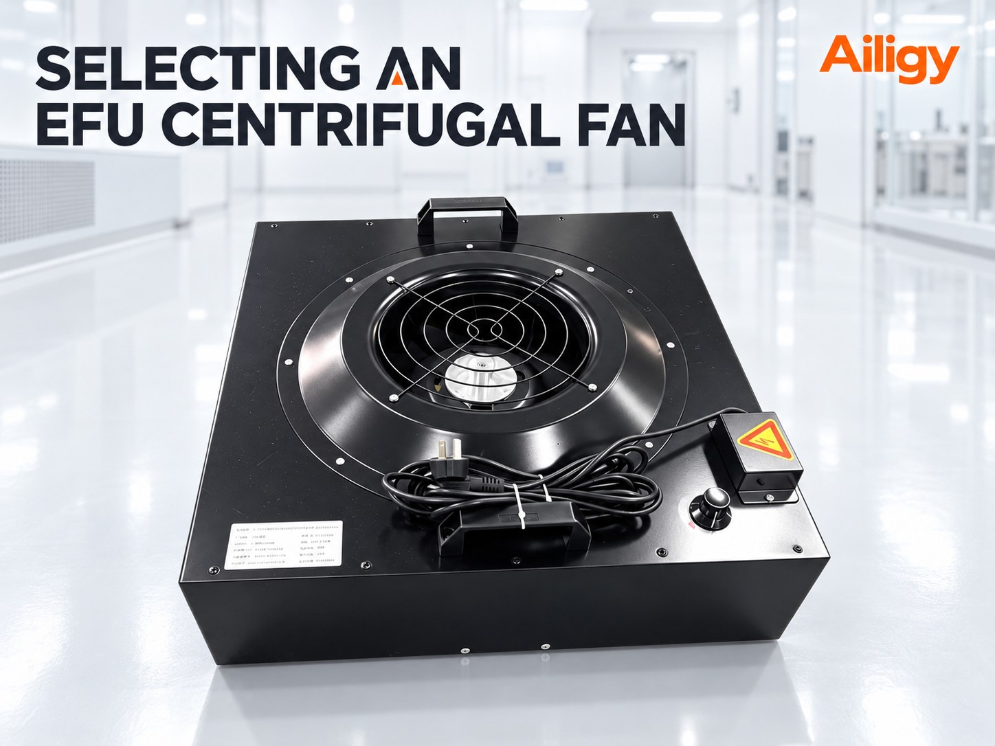 The EFU centrifugal fan should provide the required air volume under the target system resistance, taking into account speed adjustment margin, efficiency, noise and temperature rise. The same fan diameter or motor power does not mean the same performance of the whole machine.
-
 The DC motor and fan of the ultra-thin EFU need to be matched around the target operating point. DC power systems are beneficial to speed regulation and energy consumption management, but the temperature rise under high resistance, continuous operation and compact space still needs to be verified.
-
 How does EFU implement PWM speed regulation? Frequency, duty cycle and air volume calibration methodFocusing on 'How EFU realizes PWM speed regulation', this article explains the key points of signal definition, wiring requirements, duty cycle and air volume calibration, frequency selection, abnormal status, debugging method and matching of the whole machine. It also provides drawing confirmation, prototype testing and batch curing suggestions for direct verification by equipment design, procurement and maintenance personnel. Aili Industries' EFU manufacturing system covers motors, fans, filters, sheet metal and self-developed controls. The interface, calibration and complete machine verification of PWM speed regulation can be completed in the same system. When implementing EFU PWM speed regulation, you can refer to the control and interface supporting instructions provided by Aili Industries by model.
-
 This article focuses on the 0-10V speed regulation implementation method of EFU, explaining that analog control involves four levels: signal wiring, control mode switching, speed calibration and abnormal status setting. The article introduces the wiring method of the 0-10V input terminal, common terminal and speed feedback signal, explains the method of selecting the analog control mode through DIP switches or parameters, gives the steps of speed calibration and confirmation of the corresponding relationship between voltage and speed, and analyzes suggestions for handling abnormal situations such as signal disconnection, over-range, and fluctuation. The article also lists the information required for 0-10V speed regulation configuration and introduces Aili Industries’ supporting capabilities in EFU control systems to facilitate equipment-side projects to complete the configuration and debugging of EFU analog speed regulation.
-
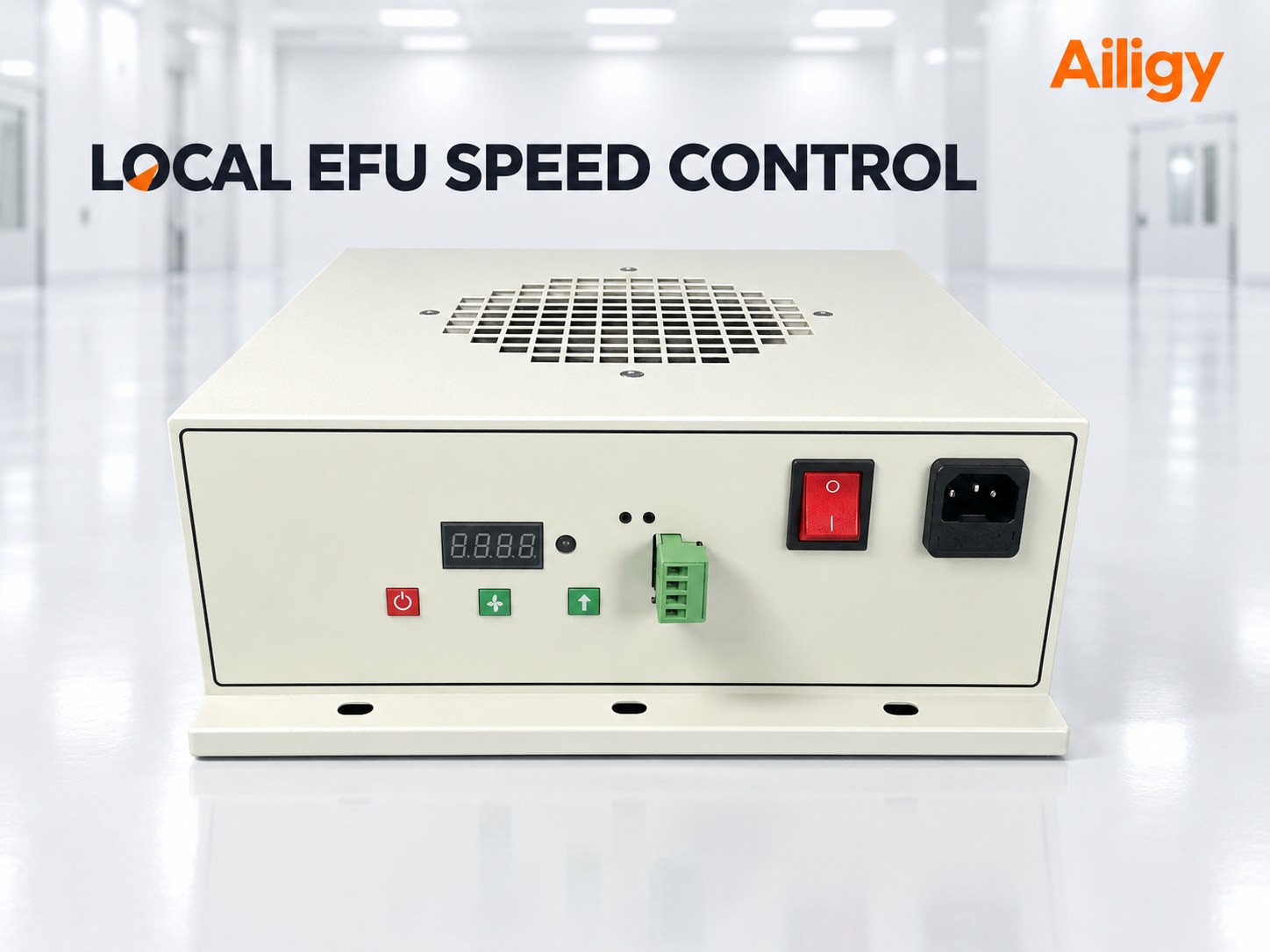 EFU local speed adjustment can be achieved through knobs, buttons or touch controllers. During debugging, you should not only record the rotational speed percentage, but also solidify the air volume, wind speed, power and noise corresponding to each gear.
-
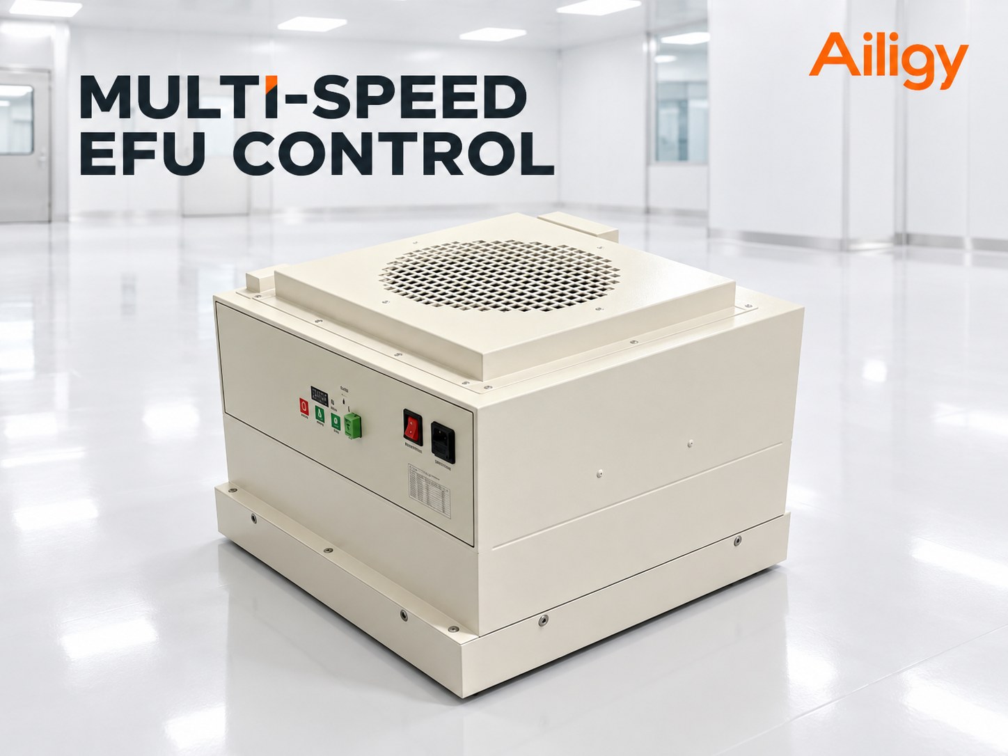 For multi-speed control of multiple EFUs, the cleanliness target of each mode should first be defined, and then the partition, rotation speed, switching conditions, communication address and exception strategy should be determined. The same mode name does not mean that all areas use the same rotation speed.
-
 The failure of the EFU to start is not necessarily caused by motor damage, but may also be caused by power interruption, missing start and stop instructions, abnormal speed control signals, communication errors, equipment interlocking or controller protection. This article explains the safety troubleshooting method for EFU not starting in the order of power supply, control signal, communication, protection status, fan mechanical structure and motor drive, and provides inspection paths corresponding to different fault manifestations.
-
 Increased EFU vibration may be caused by dust accumulation or damage to the impeller, abnormality of the motor and bearings, loose fixation, insufficient stiffness of the equipment frame, obstruction of the air inlet, or resonance at a specific speed. Based on different vibration manifestations, this article provides a troubleshooting sequence from the installation structure, speed test, filter, impeller to motor, and explains the air volume, sealing and operation items that need to be retested after treatment.
-
 If the EFU air volume decreases, you should first confirm the measurement method and control gear, and then check the air inlet, filter pressure difference, fan speed and equipment structure. Directly increasing the RPM may mask blockages or component anomalies.
-
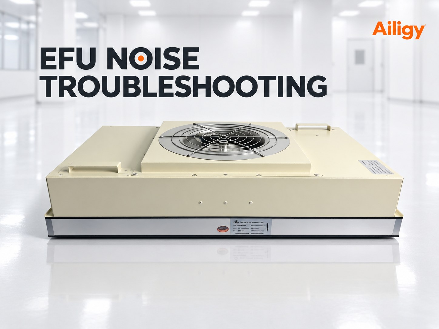 When EFU noise increases, you need to first determine whether the sound changes with rotation speed, air volume or structural contact. Obstructed inlet and high resistance are mostly manifested as aerodynamic noise, impeller or bearing abnormalities are mechanical problems, and looseness and resonance are related to the installation structure.
-
 Insufficient EFU air inlet space will increase the fan inlet resistance, leading to a decrease in actual air volume, uneven outlet wind speed, increased noise, and inconsistent performance of different equipment. This article explains the inspection methods of air inlet shielding, guard openings, side air inlets and air inlet spaces shared by multiple units, and introduces corrective measures such as increasing headroom, expanding openings, moving shields, adjusting the air inlet direction and re-matching working points.
-
 The EFU installation location cannot be determined solely based on free space. Ensure that the air inlet is unobstructed, the air outlet covers critical process areas, the structure is load-bearing, wiring is accessible, and filters and fans are accessible for maintenance.
-
 The EFU installation load-bearing inspection not only confirms the static weight, but also pays attention to the distribution of fixed points, frame stiffness, sealing surface deformation, transportation shock and operating vibration to avoid structural problems affecting airflow and sealing.
-
 The focus of configuring EFU for lithography equipment is not to simply increase the air volume, but to establish stable, well-directed and verifiable local clean airflow around sensitive areas such as wafer transportation, positioning, and detection. The article introduces the design method from the aspects of pollution path, air supply boundary, wind speed uniformity, spatial interface, filtration configuration and equipment linkage.
-
 Explain the EFU configuration method around the etching equipment environment, air supply organization, materials and maintenance requirements.
-
 Semiconductor front-end equipment EFU should be configured around key process areas. The key points of selection include the internal space of the equipment, air supply coverage, wind speed uniformity, filtration efficiency, structural shielding, maintenance direction and control linkage.
-
 EFUs used in EFEM should protect areas related to wafer transfer and loading. Selection needs to evaluate the head space, manipulator shielding, target wind speed, filter resistance, return air path and control interface in the same equipment diagram.
-
 Focusing on 'How to choose EFU and high-efficiency air supply vents', this article explains the installation conditions, operating costs, filtration configurations, control methods, maintenance differences and the judgment method of applicable scenarios. It also provides the key points for comparing the same working conditions and interface verification for direct verification by equipment design, procurement and maintenance personnel. Aili Industrial's manufacturing system covers EFU complete machines and filtration packages. Motors, fans, filters, sheet metal and controls can be checked according to project conditions in the same system. When comparing EFU and high-efficiency air supply outlets, you can refer to the complete machine and filtration package instructions provided by Aili Industrial by model.
-
 DC EFU usually has better speed regulation and equipment linkage capabilities, and is suitable for equipment projects that require multi-speed operation, continuous speed regulation and energy consumption management; AC EFU can be used for equipment under fixed working conditions or with established AC power supply and control conditions. This article combines air volume, static pressure, operating time, control method and modification conditions to explain the actual differences and selection methods of the two types of EFU.
-
 Compare the applicable boundaries of ultra-thin and conventional EFU from the perspective of installation height, airflow performance and maintenance conditions.
-
 When space is limited and deep integration with production equipment is required, EFU is usually more convenient to customize according to size and interface; when the air supply range is large and the installation boundary is relatively standard, FFU solutions can be compared. The final decision should be based on working conditions and drawings.
-
 EFU comes with its own fan and filter, which can supply air independently or in conjunction with the equipment; high-efficiency air supply outlets usually rely on centralized air conditioners or air ducts to provide air. The key to selection is whether the site has air ducts and static pressure, whether stand-alone speed regulation and equipment integration are required.
| Parameter category | What needs to be provided | Parameter category | What needs to be provided |
| Application equipment | Device name and usage area | Installation space | Available length, width, height |
| target cleanliness | Cleanliness level and process requirements | Air parameters | Air volume, wind speed, static pressure |
| Filtering requirements | H13, H14, U15, U16, etc. | Equipment drawings | Installation hole location and interference structure |
| Power supply conditions | Voltage, frequency and wiring method | control requirements | Speed regulation, communication and equipment linkage |
| Cabinet requirements | Materials, finishes and construction | Maintenance method | Filter and fan maintenance directions |
| Number of items | Prototype and batch requirements | Testing requirements | Air volume, noise, uniformity, etc. |
EFU technical support
As a professional EFU equipment-side fan filter unit for the entire industry chain, what kind of technical support can Aili Industry provide?
Equipment selection support
Assist in determining the basic specifications of EFU based on the internal space of the equipment, target cleanliness, air supply area, air volume, wind speed, static pressure and filtration efficiency.
Structure and interface support
Check the EFU length, width and height, installation hole positions, air inlet and outlet directions, fixing methods, maintenance directions and structural interference according to the equipment drawings.
Air volume and airflow support
Combined with the key process areas and structural shielding inside the equipment, confirm the air supply range, target wind speed and wind speed uniformity requirements.
Filter configuration support
Select filter efficiency, size and sealing based on particle control objectives, equipment space, available static pressure and inspection requirements.
Electrical and Control Support
Confirm the input power supply, speed control mode, communication interface, device address, partition logic and linkage requirements with the main equipment control system.
Prototype and batch project support
For ultra-thin, small size or special performance EFU, the configuration can be solidified through confirmation drawings, technical parameters and prototype testing, and then used for subsequent mass production.


Contact us now
Contact us now
