


-
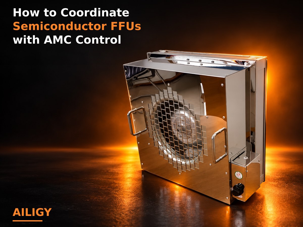 HEPA or ULPA in semiconductor FFU mainly controls particulate matter; AMC gaseous pollution control requires separate evaluation of chemical filtration. The two filtration tasks are different, and increasing the particle filtration level cannot replace target gas treatment. This article explains pollution identification, resistance superposition, system division of labor, and organizes project verification data and on-site judgment points. Aili Industrial has complete production capabilities in FFU complete machines, high-efficiency filters and chemical filters. It can provide supporting solutions for particle filtration and chemical filtration for semiconductor projects, helping projects complete system division of labor and selection verification on the premise of clarifying the type of pollution.
-
 The internal space of EFEM equipment is compact, and FFU needs to meet the internal clearance, air circulation path and cleanliness level requirements. The EFEM microenvironment usually requires high cleanliness, and the FFU layout needs to be coordinated with the wafer handling mechanism, return air path, and pressure control. This article explains space verification, airflow organization, and cleanliness levels, and organizes project verification data and on-site judgment points. Aili Industrial has complete production capabilities in terms of FFU complete machines and equipment-end supporting equipment, and can provide ultra-thin or customized air supply solutions based on the internal structure of EFEM. Welcome to contact Aili Industrial for project support.
-
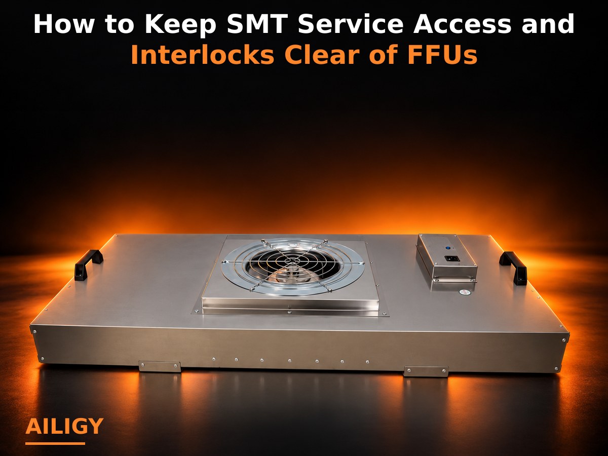 When installing FFU on SMT equipment, the cover opening trajectory, maintenance actions and safety interlocking should be checked at the same time. Just confirming that the equipment can be placed on the top may still affect operator inspection or the protective function of the original equipment. This article explains space verification, interlocking boundaries, trial installation verification, and organizes project verification data and on-site judgment points. Aili Industry adopts a full industry chain production and customization model, which can match the FFU machine, filter, controller and installation structure according to equipment conditions, helping electronics factories take into account clean air supply, maintenance space and safe operation in a limited space.
-
 When using FFU in an SMT workshop, it is necessary to check the air volume, static pressure, filtration level, noise, air supply uniformity and control method based on process dust generation, equipment heating and operating actions. Parameters should be compared between the whole machine and the system, not just a single value. This article explains parameter verification, working condition correspondence, system cooperation, and organizes project verification data and on-site judgment points. Aili Industrial has complete production capabilities in FFU supporting areas in the electronics industry and can provide selection solutions based on SMT workshop conditions. Welcome to contact Aili Industrial for project support.
-
HEPA or ULPA in semiconductor FFU mainly controls particulate matter; AMC gaseous pollution control requires separate evaluation of chemical filtration. The two filtration tasks are different, and increasing the particle filtration level cannot replace target gas treatment. This article explains pollution identification, resistance superposition, system division of labor, and organizes project verification data and on-site judgment points. Aili Industrial has complete production capabilities in FFU complete machines, high-efficiency filters and chemical filters. It can provide supporting solutions for particle filtration and chemical filtration for semiconductor projects, helping projects complete system division of labor and selection verification on the premise of clarifying the type of pollution.
-
The internal space of EFEM equipment is compact, and FFU needs to meet the internal clearance, air circulation path and cleanliness level requirements. The EFEM microenvironment usually requires high cleanliness, and the FFU layout needs to be coordinated with the wafer handling mechanism, return air path, and pressure control. This article explains space verification, airflow organization, and cleanliness levels, and organizes project verification data and on-site judgment points. Aili Industrial has complete production capabilities in terms of FFU complete machines and equipment-end supporting equipment, and can provide ultra-thin or customized air supply solutions based on the internal structure of EFEM. Welcome to contact Aili Industrial for project support.
-
 Rated power cannot be directly equated to long-term operating power consumption. The actual energy consumption is also related to rotation speed, static pressure, filter resistance, operating mode and working time. When evaluating FFU operating costs, the input power and annual operating hours in working, on-duty and low-speed modes should be measured separately.
-
 FFU static pressure reflects the equipment's ability to overcome the resistance of filters, boxes and external systems. When the static pressure is insufficient, even if the nominal air volume of the fan is large, it may not be able to maintain the target air supply volume on site. Therefore, the available static pressure corresponding to the target air volume should be checked when selecting the model.
-
 The rated air volume is a reference value measured under specified rotation speed, filter and test environment. The actual operating air volume will vary with filter resistance, system static pressure, installation conditions and control gears. Clean room design and acceptance should be based on the air volume at the actual working point, rather than directly using the maximum value in the product catalog.
-
 The FFU parameter table should focus on the rated air volume, working wind speed, static pressure, input power, noise, filter efficiency, filter resistance and speed adjustment range. At the same time, it is necessary to confirm the test conditions corresponding to these parameters to avoid confusing the maximum air volume, rated air volume and on-site working air volume.
-
 How should the air volume and static pressure match when FFU is used for filter pressure difference?After the pressure difference increases, the fan speed can be adjusted within the allowable range to compensate for part of the air volume loss, but the speed cannot be increased indefinitely. If the pressure difference is close to the replacement criterion or the equipment power and noise increase significantly, the filter should be checked and replaced.
-
 When selecting a model, you should not only confirm the air volume under the initial resistance, but also evaluate whether the FFU can maintain the basic air supply demand after the resistance gradually increases. The fan and control system need to retain appropriate adjustment capabilities to avoid a rapid drop in air volume after the filter has been used for a period of time.
-
 The filter's initial pressure difference, operating pressure difference, recommended final resistance value, corresponding air volume and fan speed should be recorded. It is not enough to record the pressure difference alone. It is necessary to combine the changes in air volume and operating time to determine the filter status and replacement time.
-
 The filter should be comprehensively selected based on the cleanliness target, particle control requirements, target air volume, allowable resistance, installation structure and testing requirements; when the efficiency level changes, the resistance and fan operating point must be checked simultaneously. This article further expands from aspects such as parameter matching, filtering system, installation control, common misunderstandings, procurement information, and Aili Industrial FFU project supporting capabilities.
-
 FFU should determine the air volume and static pressure based on the overall fan performance, filter resistance and target operating point; the efficient air supply outlet needs to be calculated from the total air volume of the centralized air supply system, pipe resistance and terminal residual pressure. The same selection method cannot be directly applied to the two.
-
 Both types of equipment can be equipped with high-efficiency or ultra-high-efficiency filters, but the filter resistance is borne by different power systems. FFU needs to check the working point of its own fan, and for high-efficiency air supply outlets, it is necessary to confirm the available static pressure and air volume distribution at the end of the air conditioning system.
-
 When there is stable centralized air supply and sufficient system static pressure, efficient air supply outlets can be evaluated; when independent power, flexible partitioning or later expansion is required, FFU can be considered. The final choice also takes into account ceiling, piping, energy consumption and control requirements.
-
 It is necessary to compare the power source, available static pressure, air supply volume, filter configuration, installation space, independent adjustment capability, control method and maintenance conditions. FFU has its own power, and high-efficiency air supply vents usually rely on centralized air supply systems. The applicable system structures of the two are different.
-
 It can be partitioned according to production lines, process sections, rooms or operating shifts, and work, duty and shutdown status can be set respectively. The zoning plan needs to be coordinated with the air supply and return air, room pressure difference and equipment start and stop logic to prevent local shutdowns from affecting adjacent areas.
-
 When the dust load is high, pre-filtration measures can be set according to particle characteristics, and an end filter with appropriate dust holding capacity and resistance characteristics can be selected. Changes in pressure difference and air volume should be recorded during operation to avoid rapid blockage of the filter, which will lead to a continued decrease in air supply volume.
-
 High air volume projects should not only increase the fan speed, but also check the static pressure, power, noise and wind speed uniformity under the target air volume. For special production lines, high-wind speed FFU can be configured according to space and process requirements, but the operating status of the entire machine should be confirmed through prototype testing.
-
 Lithium battery workshops should focus on dust load, target wind speed, filter dust holding capacity, continuous operation time and maintenance cycle. Some production lines also require higher air supply volume, so the FFU fan residual pressure, filter resistance and structural protection requirements should be checked at the same time.
-
 The coverage rate determines the distribution basis of FFU on the ceiling, the air volume affects the regional air supply capacity, and the static pressure ensures that the equipment maintains the designed air volume under the resistance of the filter. The three should be determined together with airflow simulation, empirical calculations or field tests to avoid only improving coverage.
-
 The selection of H14 or ULPA should be determined based on process risks, control particle size, project standards and testing requirements. Not all ISO 5 projects must use the same filtration level. When selecting a higher efficiency filter, the resistance and FFU fan residual pressure must be rechecked.
-
 When configuring FFU in an ISO 5 clean room, you need to confirm the room area, floor height, process dust generation, number of personnel, target wind speed, ceiling coverage and return air method. The filter grade, actual air volume of a single unit, and regional air volume uniformity also need to be confirmed through design and testing.
-
 It is recommended to make a comprehensive judgment from the dimensions of cleanliness target, actual working conditions, FFU air volume and static pressure, filter resistance, installation space, control method and subsequent maintenance, and confirm with test data under agreed working conditions. This article further expands from aspects such as parameter matching, filtering system, installation control, common misunderstandings, procurement information, and Aili Industrial FFU project supporting capabilities.
-
 The FFU air volume should meet the corridor air supply and pressure difference requirements, while the static pressure must overcome the filter and installation resistance. The position of the return air outlet needs to ensure that the air can flow in the designed direction to avoid local short circuit of the supply air and insufficient ventilation at the far end.
-
 Filtration levels should be determined based on adjacent clean areas, material or personnel traffic risks, and project standards. Corridor operating time, dust load and maintenance conditions should also be considered when selecting filters to avoid a mismatch between efficiency levels and actual control targets.
-
 The quantity should be determined based on the corridor volume, target ventilation, pressure difference requirements and the actual air volume of a single unit, and then the location should be adjusted based on doorways, corners and high-frequency traffic areas. Long and narrow corridors require special attention to the air volume distribution and return air distance along the way.
-
 Clean corridors need to pay attention to length, width, floor height, traffic frequency, pressure difference between adjacent rooms, air supply and return position and the impact of door opening. The FFU layout should avoid the formation of local low wind speed areas and maintain airflow from cleaner areas to the target direction.
-
 Static pressure reflects the FFU's ability to overcome filter and system resistance and maintain target air supply. It makes more sense to check the available static pressure corresponding to the target air volume, rather than comparing one static pressure number in isolation. Focusing on 'how to determine the operating status of FFU through air volume and static pressure testing', to deal with this problem, the project goals should be determined first, then the calculation or inspection sequence should be established around the design air volume and actual air volume, and finally verified through prototype, factory testing or field data. The key is to write the design values, equipment operating points and acceptance methods in the same set of technical conditions.
-
 The filter should be comprehensively selected based on the cleanliness target, particle control requirements, target air volume, allowable resistance, installation structure and testing requirements; when the efficiency level changes, the resistance and fan operating point must be checked simultaneously. It is necessary to check the filter resistance, installation direction, sealing status and surface contamination, but the fan speed, control gear, air inlet obstruction and measurement method cannot be ignored. The source of the abnormality can be determined through joint judgment of pressure difference, air volume and electrical data.
-
 Focusing on 'how to formulate an air volume test and sampling plan for multiple FFU systems', to deal with this problem, the project goals should be determined first, then the calculation or inspection sequence should be established around the design air volume and actual air volume, and finally verified through prototypes, factory tests or on-site data. The key is to write the design values, equipment operating points and acceptance methods in the same set of technical conditions. This article focuses on the design air volume and actual air volume, explains the data that needs to be checked, project implementation sequence, acceptance records and common deviations, and helps clean engineering, equipment matching and purchasing personnel form executable judgments.
-
 Test records should include equipment number, operating gear, measuring point location, wind speed or volume, filter status, test equipment and environmental conditions. Multiple devices also need to record the data of each device and the regional average value to facilitate the judgment of consistency and air volume balance.
-
 FFU implements communication between multiple devices through RS485, which requires unified wiring methods, address settings and communication protocols. Bus topology, termination resistors and shielding grounding all affect communication stability. This article explains wiring verification, address allocation, protocol matching, and organizes project verification data and on-site judgment points. Aili Industrial has complete self-research capabilities in FFU control systems and can provide RS485 communication solutions and debugging support. Welcome to contact Aili Industrial for project support.
-
 The device address of the FFU centralized control system should be planned in a unified manner based on the partition, installation location and communication protocol. Unclear or conflicting address allocation may cause the group control to fail to recognize the device or cause control errors. This article explains the numbering rules, partition correspondence, conflict troubleshooting, and organizes project verification data and on-site judgment points. Aili Industrial has complete self-research capabilities in FFU control systems and can provide address planning solutions based on project scale. Welcome to contact Aili Industrial for project support.
-
 Voltage stability, line voltage drop and control settings will affect the actual operating status of the motor, thereby affecting the FFU air volume and static pressure. During project debugging, power supply conditions and air performance should be measured simultaneously to avoid misdiagnosing electrical problems as filter or fan problems.
-
 Focusing on 'How to calculate the number of loops and power distribution capacity for multiple 220V FFU projects', to deal with this problem, the project goals should be determined first, and then the calculation or inspection sequence should be established based on dividing the total demand air volume by the actual air volume of a single machine, and finally verify it through prototypes, factory testing or field data. The key is to write the design values, equipment operating points and acceptance methods in the same set of technical conditions. This article focuses on dividing the total demand air volume by the actual air volume of a single machine, explaining the data that needs to be checked, project implementation sequence, acceptance records and common deviations, helping clean engineering, equipment supporting and purchasing personnel to form executable judgments.
-
 The air volume, pressure difference, input power, operating time and cleanliness results before and after the transformation should be recorded under similar production loads and filter conditions. Only through the energy consumption per unit air supply volume and annual operation data can we judge whether the transformation has achieved the expected goals.
-
 Before modification, record the air volume, static pressure, power, noise, operating time and control mode of the original system, and check the size, power supply and control compatibility of the new equipment. Energy saving judgments should be based on operating data under the same air supply task, rather than just comparing motor names.
-
 It is necessary to check the controller capacity, communication address range, power supply loop, protocol compatibility and software partitioning capabilities. If the original system lacks expansion margin, some equipment can be retained and independent control areas can be added, or the control system can be upgraded as a whole.
-
 Before expansion, the total air supply volume, actual air volume of existing FFU, room pressure difference, return air capacity, ceiling load-bearing capacity, and power supply and distribution capacity should be recalculated. It is also necessary to evaluate whether the new equipment will change the original air flow balance and control system load.
-
 The test should measure the air volume and static pressure corresponding to different resistance points under the agreed filter and rotation speed conditions. After the target operating point meets the requirements, the power, noise and wind speed distribution should also be checked to avoid verifying only a single air volume data.
-
 Changes in the design air volume will change the filter face velocity and operating resistance, so the filter size, efficiency grade and rated air volume need to be rechecked. If the filter area is insufficient, problems such as increased resistance, increased noise, or shortened service life may occur.
-
 First calculate the total air supply volume of the clean room, then select the specifications and determine the quantity based on the size of the ceiling and the actual working air volume of a single FFU. The calculation results need to be adjusted based on the equipment layout, return air position and regional cleanliness requirements, and cannot just be a simple division.
-
 The design air volume can be determined based on the room volume, ventilation requirements, one-way flow area, target wind speed and process dust volume. The effective air supply ratio, equipment occlusion, leakage and operating margin should also be considered when calculating, and the design status and acceptance status should be clarified.
-
The FFU air volume should meet the corridor air supply and pressure difference requirements, while the static pressure must overcome the filter and installation resistance. The position of the return air outlet needs to ensure that the air can flow in the designed direction to avoid local short circuit of the supply air and insufficient ventilation at the far end.
-
Filtration levels should be determined based on adjacent clean areas, material or personnel traffic risks, and project standards. Corridor operating time, dust load and maintenance conditions should also be considered when selecting filters to avoid a mismatch between efficiency levels and actual control targets.
-
The quantity should be determined based on the corridor volume, target ventilation, pressure difference requirements and the actual air volume of a single unit, and then the location should be adjusted based on doorways, corners and high-frequency traffic areas. Long and narrow corridors require special attention to the air volume distribution and return air distance along the way.
-
Clean corridors need to pay attention to length, width, floor height, traffic frequency, pressure difference between adjacent rooms, air supply and return position and the impact of door opening. The FFU layout should avoid the formation of local low wind speed areas and maintain airflow from cleaner areas to the target direction.
-
 The FFU operating mode, air volume, filter integrity, room pressure difference and air conditioning system status should be confirmed before verification. During the verification process, wind speed, particle concentration, pressure difference and related test records need to be retained so that the equipment operating status and verification results can correspond to each other.
-
 The total air supply volume should be calculated first based on the workshop area, floor height, ventilation requirements and internal dust load, and then the quantity should be determined based on the actual air volume of a single FFU. When laying out, avoid obstruction by large equipment and coordinate with the return air position to form a stable airflow path.
-
 Filter selection should be based on cleanliness level, risk area, detection requirements and system resistance, while confirming filter sealing, leak detection methods and replacement conditions. For areas with special biosecurity requirements, equipment plans need to be determined based on project risk assessment.
-
 Pharmaceutical cleanrooms need to comprehensively consider cleanliness levels, room pressure differences, airflow organization, filtration integrity, cleaning and disinfection and verification requirements. The FFU configuration should also be coordinated with the operating strategies of the air conditioning system, production status and non-production status.
-
 Mode switching should be performed in regional and time order to avoid room pressure fluctuations caused by a large number of FFU changing rotational speeds at the same time. Control can be optimized through delayed start, group switching and pressure difference feedback, and the switching process can be recorded during the commissioning phase.
-
 In low-speed mode, the residual pressure that the fan can provide is smaller. After the filter resistance increases, the air volume decreases may be more obvious. When setting the working and duty speeds, the resistance change of the filter from the initial state to the later period of use should be considered.
-
 Zone operation strategies can be formulated based on process areas, production shifts and pressure differences. The shutdown sequence cannot destroy the pressure difference between adjacent areas. The duty mode should also retain necessary air circulation, and record the start and stop times and set values of each area.
-
 The working mode should meet the requirements for cleanliness, air volume and pressure difference under production conditions, while the duty mode should be combined with pollution control and energy consumption management settings during non-production periods. Both modes require clear rotation speed, operating period and switching conditions.
-
 Whether FFU uses HEPA or ULPA filters should be judged based on the target cleanliness level, process sensitivity and filter resistance. ULPA is more efficient, but the resistance may increase, and the fan operating point needs to be checked. This article explains efficiency correspondence, resistance verification, scenario selection, and organizes project verification data and on-site judgment points. Aili Industry has complete production capabilities in FFU complete machines and high-efficiency filters, and can provide HEPA and ULPA filter configuration solutions. Welcome to contact Aili Industry for project support.
-
 After the filter grade is increased, the density and structural changes of the filter material may increase the resistance and affect the FFU operating point and air volume. To improve the filtration level, you can't just look at efficiency, but also need to recheck the fan static pressure and air volume. This article explains resistance changes, working point verification, complete machine matching, and organizes project verification data and on-site judgment points. Aili Industrial has complete production capabilities in FFU complete machines and high-efficiency filters, and can cooperate with the project to check the matching of filters and complete machines. Welcome to contact Aili Industrial for project support.
-
 The filter size, sealing method, efficiency, initial resistance and actual air volume should be checked, and the installation effect should be confirmed through leak detection and wind speed testing. After replacing different filters, also observe whether the air volume, power and noise change significantly.
-
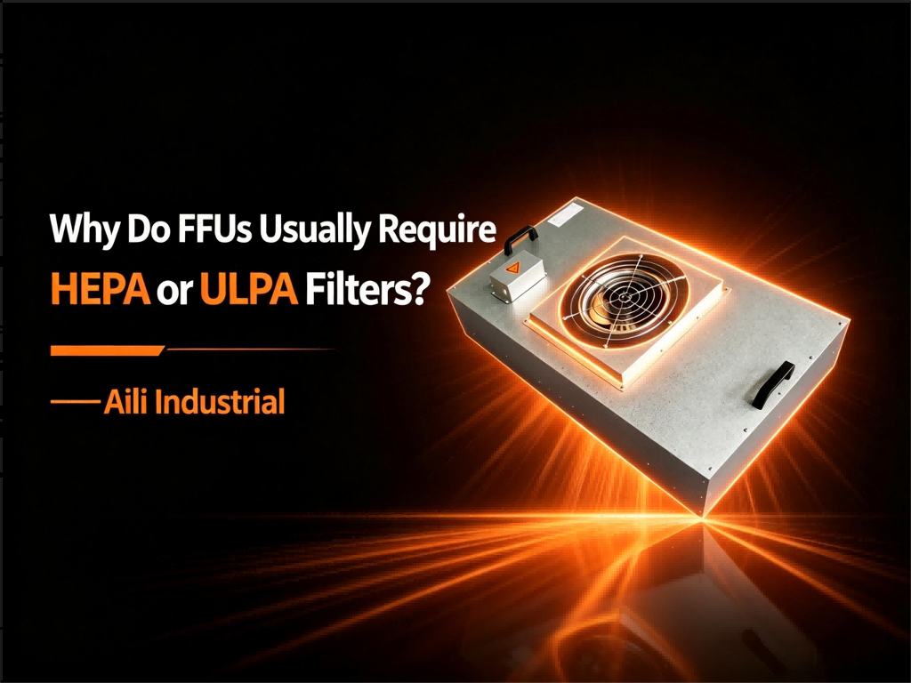 FFU requires a terminal filter to remove fine particles from the supply air to provide filtered air to the clean area. The specific selection of HEPA or ULPA filters depends on the cleanliness level and process requirements, and must match the air volume, static pressure and installation sealing method of the FFU.
-
 FFU selection needs to comprehensively consider the application scenario, installation size, air volume, wind speed, HEPA/ULPA filtration level, filter and system resistance, AC/DC/EC power solution, control method, box structure and actual use environment. For space-limited applications such as semiconductor equipment, EFEM, and SMT, ultra-thin EFUs can be considered based on the equipment structure; for high wind speeds or higher cleanliness requirements, fans and HEPA/ULPA filters need to be rematched; for multiple FFU projects, FFU group control systems should be planned simultaneously. Aili Industrial can match FFU, EFU, filters and control systems based on actual project conditions.
-
 Prototypes can identify size, performance, control and installation issues before series production. The test conditions must be agreed in advance, including filter status, air volume point, static pressure, rotation speed and detection method, to avoid unclear qualification standards for prototypes.
-
 Before purchasing FFU, the clean room area, floor height, target cleanliness, ceiling openings, installation quantity, air volume and speed, filtration level, material, power supply and control requirements should be provided. Non-standard projects should also provide equipment drawings, interface dimensions, maintenance directions and communication requirements so that manufacturers can complete accurate selection.
-
 The rated air volume usually corresponds to the specified test conditions. The actual air volume after FFU installation will also be affected by filter resistance, fan speed, return air conditions and system resistance. When selecting, more attention should be paid to the working air volume that can be achieved under the target static pressure and the adjustment margin after the filter resistance increases.
-
 First determine the air supply volume and target wind speed according to the process area, then calculate the filter and system resistance, and select the FFU that can operate at this working point. The control system is planned according to area, quantity, operation mode and expansion demand, so that the air performance and group control strategy can be implemented simultaneously.
-
 Filter selection should be determined based on process sensitivity, target particle size, cleanliness level, leak detection requirements and acceptable resistance. Different levels can be used in different process areas, but the testing standards should be unified and the performance of the filter and FFU fan should be matched.
-
 The specifications and quantity should be determined based on the area of the process area, target air flow, equipment layout and the actual air volume of a single FFU. The ceiling layout needs to take into account the uniformity of wind speed, lighting fire-fighting facilities, maintenance access and subsequent equipment expansion.
-
 For new projects, the cleanliness level, ceiling module, FFU coverage, target wind speed, filtration level, operation mode and group control requirements of each process area should be confirmed. It is also necessary to reserve adjustment space based on equipment heating, dust generation and phased production plans.
-
 The technical agreement should specify the target air volume, corresponding static pressure, filter status, fan speed, allowable deviation and test method. The maximum air volume and the maximum static pressure cannot be simply juxtaposed, otherwise it may form a working point that cannot be reached at the same time.
-
 The purchase list should itemize the equipment name, specifications and sizes, quantity, air volume and static pressure, filter, box material, power mode, control interface and accessories. Non-standard equipment should also be associated with confirmation drawings to avoid just writing an internal model without a technical definition.
-
 Inquiry information should include quantity, overall dimensions, air volume, static pressure, filtration level, material, power supply, control method, installation direction and acceptance requirements. The more complete the information, the easier it is to effectively compare the configurations quoted by different suppliers.
-
 In addition to the complete FFU machine, the budget should also include the cost of filters, controllers, communication equipment, cables, installation auxiliary materials, transportation, debugging, testing and spare parts. Renovation projects also need to consider costs such as dismantling, interface adjustments, and shutdown construction.
| Parameter category | What needs to be provided | Parameter category | What needs to be provided |
| Usage scenarios | Clean room, clean shed or equipment end | target cleanliness | ISO level or project requirements |
| Installation space | Ceiling dimensions, openings and available heights | Single unit requirements | Air volume, wind speed and static pressure |
| Filtering requirements | H13, H14, U15, U16, etc. | Cabinet requirements | Galvalume plate, spray plastic or stainless steel |
| Power supply conditions | Voltage, frequency and wiring methods | Speed regulation method | Multi-speed, stepless or centralized speed regulation |
| control requirements | Single machine, regional or computer group control | Operating conditions | Working hours, temperature, humidity and environment |
| Maintenance method | Top maintenance or indoor side maintenance | Customized requirements | Dimensions, interfaces and special construction |


Contact us now
